
Bus sensor

A sensor and bus technology, which is applied in the field of bus sensors, can solve the problems of the small number of sensors that can be connected to the bus and the short power supply distance of the bus, and achieve the effects of extending the power supply distance of the bus, increasing the power supply distance of the bus, and reducing the voltage drop

Pending Publication Date: 2020-04-07
TIANDI SCI & TECH CO LTD
View PDF0 Cites 0 Cited by
  • Summary
  • Abstract
  • Description
  • Claims
  • Application Information

AI Technical Summary

Problems solved by technology

However, this bus sensor has the disadvantages of a small number of sensors that can be connected to the bus and a short power supply distance of the bus.

Method used


Image

  • Bus sensor
  • Bus sensor

Examples


Embodiment Construction

[0020] In order to make the object, technical solution and advantages of the present invention clearer, the implementation manner of the present invention will be further described in detail below in conjunction with the accompanying drawings.

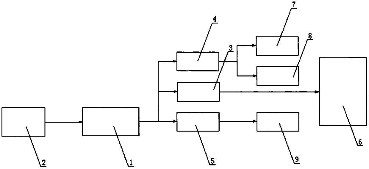
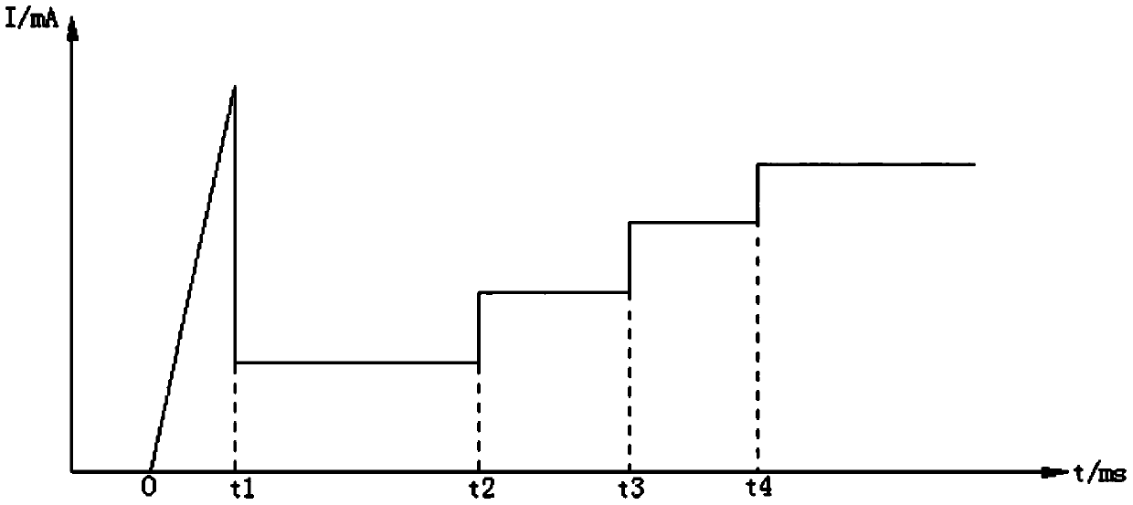
[0021] figure 1 and 2 is a preferred embodiment of the bus sensor of the present invention.

[0022] The bus sensor includes a main power supply 1, a protection resistor 2, a core power supply 3, an auxiliary power supply 4, a communication power supply 5, a core processing circuit 6, a display circuit 7, a sensing module circuit 8 and a communication circuit 9; the main power supply 1 Provide power to the core power supply 3, the auxiliary power supply 4 and the communication power supply 5, wherein the core power supply 3 maintains continuous power supply, the core power supply 3 is connected to the core processing circuit 6, and the core processing circuit 6 does not Goes to sleep while working.

[0023] In this embodiment, the a...


PUM


Abstract

A bus sensor comprises a main power supply (1), a core power supply (3), an auxiliary power supply (4), a communication power supply (5), a core processing circuit (6), a display circuit (7), a sensing module circuit (8) and a communication circuit (9), wherein the main power supply (1) supplies power to the core power supply (3), the auxiliary power supply (4) and the communication power supply (5), the core power supply (3) maintains continuous power supply, the core power supply (3) is connected with the core processing circuit (6), and the core processing circuit (6) enters a dormant statewhen not working. According to the invention, independent power supply control is added to other parts of the sensors except the core circuit, so that the sensors are powered off, and the transient current when the plurality of sensors are powered on and started is reduced by starting the sensors in a time-sharing manner, so that the number of the sensors connected with the bus can be increased.

Description

technical field [0001] The invention relates to a bus sensor. Background technique [0002] The existing underground bus sensors in coal mines belong to wired sensors, and multiple sensors are connected to the bus in parallel. Generally, a 4-core bus is used to realize long-distance bus communication and bus power supply for sensors. However, this bus sensor has the disadvantages of a small number of sensors that can be connected to the bus and a short power supply distance of the bus. Contents of the invention [0003] In order to solve the above problems, the present invention provides a bus sensor. [0004] The present invention is obtained based on the inventor's in-depth analysis of the existing technical problems. Through in-depth analysis, the inventor found that the transient output power of the mine intrinsically safe power supply powered by the bus is limited by the explosion-proof requirements and cannot be too large, especially mine cables. The distribution p...

Claims


Application Information

Patent Timeline
Patent Type & Authority Applications(China)
IPC IPC(8): H04L12/10H04L12/40H02M1/36
CPCH04L12/10H04L12/40H02M1/36
Inventor 张辉马冰高雨阳李帅王正胜吴志刚王东攀田锦州刘跃东袁伟茗孙洋伊钟玉颜丙双刘超儒
Owner TIANDI SCI & TECH CO LTD
Learn More