

Automatic mechanical paint spraying equipment
A painting equipment and mechanical technology, applied in the direction of spraying devices, etc., can solve the problems of limited painting area, noise pollution, low painting efficiency, etc., and achieve the effect of uniform painting amount, high painting quality and fast painting speed
- Summary
- Abstract
- Description
- Claims
- Application Information
AI Technical Summary
Problems solved by technology
Method used
Image

Examples
Embodiment 1
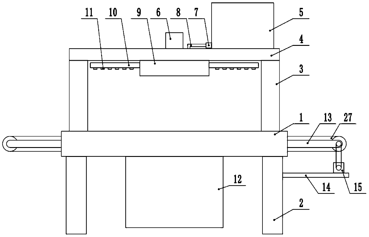
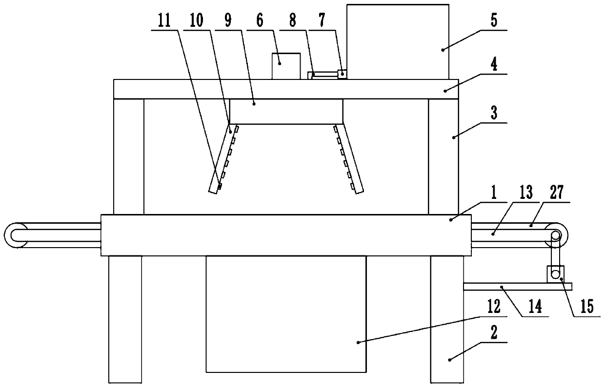
[0027] see Figure 1-4 , an automatic mechanical painting equipment, comprising a workbench 1, the bottom end of the workbench 1 is fixedly connected to a support leg 2, the top four corners of the workbench 1 are fixedly connected to a support column 3, and the top end of the support column 3 is fixed Connect the top plate 4, the center of the bottom end of the worktable 1 is provided with a rotating device 9, the rotating device 9 is connected to the spray pipe 10, and the spray pipe 10 is provided with a plurality of atomizing nozzles 11, and the top of the workbench 1 is fixed Connect the paint box 5, the bottom side of the paint box 5 is fixedly connected to the delivery pump 7, and the delivery pipe 8 is fixedly connected between the delivery pump 7 and the rotating device 9, and the workbench 1 is provided with a conveyor belt 27, so The bottom end of the workbench 1 is fixedly connected with a lifting device 12 .
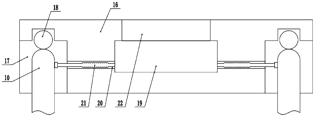
[0028] The rotating device 9 includes a rotating seat...
Embodiment 2
[0036] see Figure 1-4, The other content of this embodiment is the same as that of Embodiment 1, except that: the telescopic rod 24 includes a hydraulic telescopic rod and an electric telescopic rod. The side of the support leg 2 is fixedly connected to the fixed plate 14, and the top end of the fixed plate 14 is fixedly connected to the second drive motor 15, and the output shaft of the second drive motor 15 is connected to the conveying roller through transmission.
[0037] In the implementation process of the present invention, first the equipment to be painted is placed on the conveyor belt 27 to be transported, and when the equipment moves to the right below the rotating device 9, the telescopic rod 24 is controlled to upgrade the lifting plate 25 and the support plate 26 Lift the equipment to be painted and leave the conveyor belt, then control the third drive motor 18 to start to drive the spray pipe 10 to rotate, then control the first drive motor 6 to drive the rotat...
PUM
 Abstract
Description
Claims
Application Information