

Environment-friendly industrial coal waste recycling device
An environmentally friendly, coal-based technology, applied in steam engine installations, transportation and packaging, solid waste removal, etc., can solve the problems of insufficient solid waste recycling, consumption, waste of resources, etc., and achieve high coal recycling rate and resource consumption. The effect of low and low resource consumption
- Summary
- Abstract
- Description
- Claims
- Application Information
AI Technical Summary
Problems solved by technology
Method used
Image

Examples
Embodiment 1
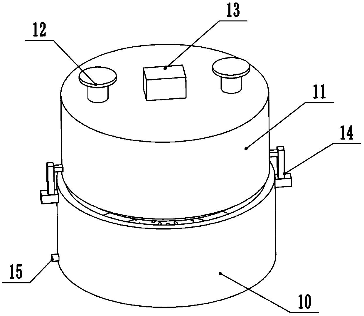
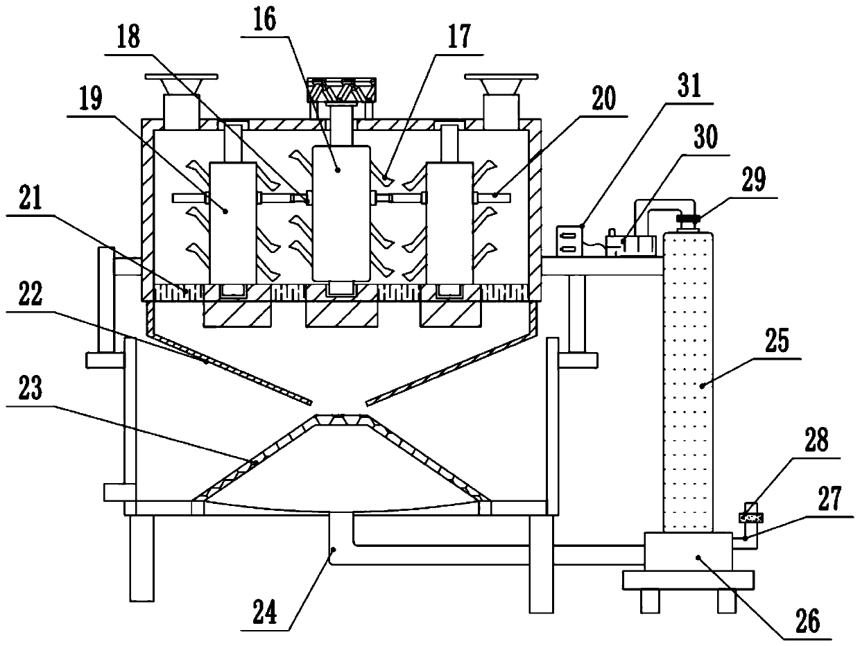
[0020] see Figure 1-2 , an environment-friendly recycling device for industrial coal waste, comprising a filter bin 10, a crushing bin 11, a feed port 12, an impurity outlet 15, and a feeding channel 22; the bottom of the filter bin 10 is fixedly supported by feet, and the filter bin 10 The upper part of the crushing bin 11 is set as an open structure, and the lower part of the side wall of the crushing bin 11 is fixedly installed above the filter bin 10 through a connecting frame 14. There are feeding ports 12 on the left and right sides of the top of the crushing bin 11, and two sets of feeding ports are set. Port 12 facilitates increased feed rates. The inner middle of the crushing bin 11 is provided with a vertical driving shaft 16, and the top of the driving shaft 16 is rotatably connected with a first motor 13 fixed on the outer top of the crushing bin 11, starting the first motor 13 can directly drive the driving shaft 16 to perform To rotate, two groups of driven sha...
Embodiment 2
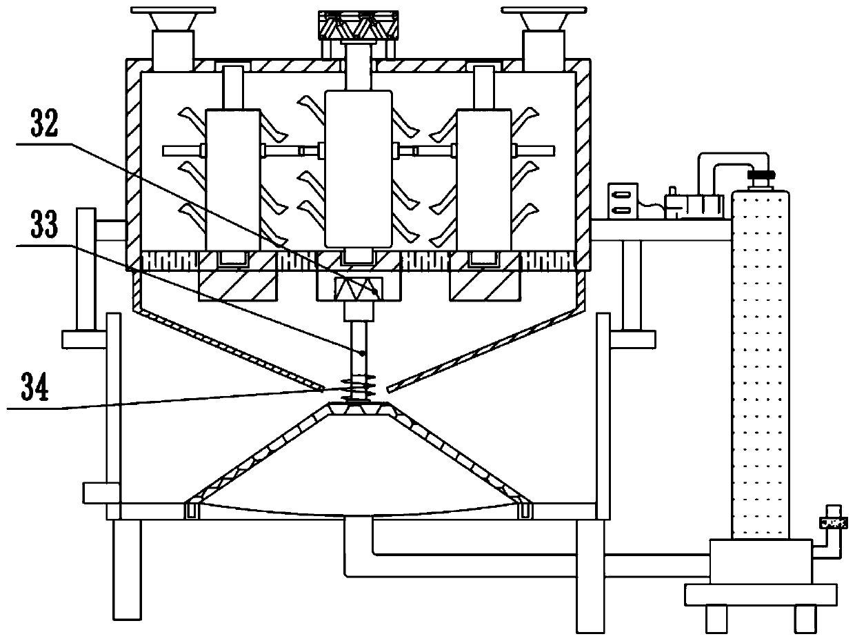
[0024] refer to image 3 , on the basis of Embodiment 1, a second motor 32 is provided on the inside of the bottom of the crushing bin 11 directly below the driving shaft 16, and the lower output end of the second motor 32 is rotatably connected to a vertical rotating rod 33, and the rotating rod The bottom end of 33 is fixedly connected to the top upper surface of filter body 23, and the bottom of described filter body 23 is rotatably connected in the rotation groove that is opened in the bottom of filter chamber 10, drives rotating rod 33 rotations by starting second motor 32, Then the filter body 23 is driven to rotate, so that the filter body 23 is in a rotating state to filter the coal waste, which can improve the filtering speed and accuracy.
Embodiment 3
[0026] On the basis of Embodiment 2, a screw rod 34 is fixedly installed on the rotating rod 33 at the opening of the lower side of the feeding channel 22, and the rotating rod 33 drives the screw rod 34 to rotate while rotating, thereby passing the screw rod 34 to the bottom. The coal waste falling at the bottom of the feeding channel 22 is stirred, thereby preventing the coal waste from clogging at the bottom of the feeding channel 22 .
PUM
 Abstract
Description
Claims
Application Information