
Manufacturing system of heat transfer pipe support strip on direct current steam generator of electric equipment

A technology for steam generators and power equipment, applied in milling machine equipment, manufacturing tools, details of milling machine equipment, etc., can solve the problems of scrapped products in batches, achieve the effect of uniform load, less error-prone, and improved surface quality

Pending Publication Date: 2020-04-10
上海瑞纽机械股份有限公司
View PDF0 Cites 0 Cited by
  • Summary
  • Abstract
  • Description
  • Claims
  • Application Information

AI Technical Summary

Problems solved by technology

There are special requirements for its processing and manufacturing. There are many factors that need to be considered in processing and manufacturing, such as the influence of gravity on installation and hoisting, the influence of manual coordinates on machining accuracy, the influence of tool cutting force and cutting heat, and These factors restrict each other, affect each other, and even interfere with each other. If one link is not handled properly, it will cause scrapping of batch products.

Method used


Image

  • Manufacturing system of heat transfer pipe support strip on direct current steam generator of electric equipment
  • Manufacturing system of heat transfer pipe support strip on direct current steam generator of electric equipment
  • Manufacturing system of heat transfer pipe support strip on direct current steam generator of electric equipment

Examples


Embodiment Construction

[0037] The present invention will be described in detail below in conjunction with specific embodiments. The following examples will help those skilled in the art to further understand the present invention, but do not limit the present invention in any form. It should be noted that those skilled in the art can make several modifications and improvements without departing from the concept of the present invention. These all belong to the protection scope of the present invention.

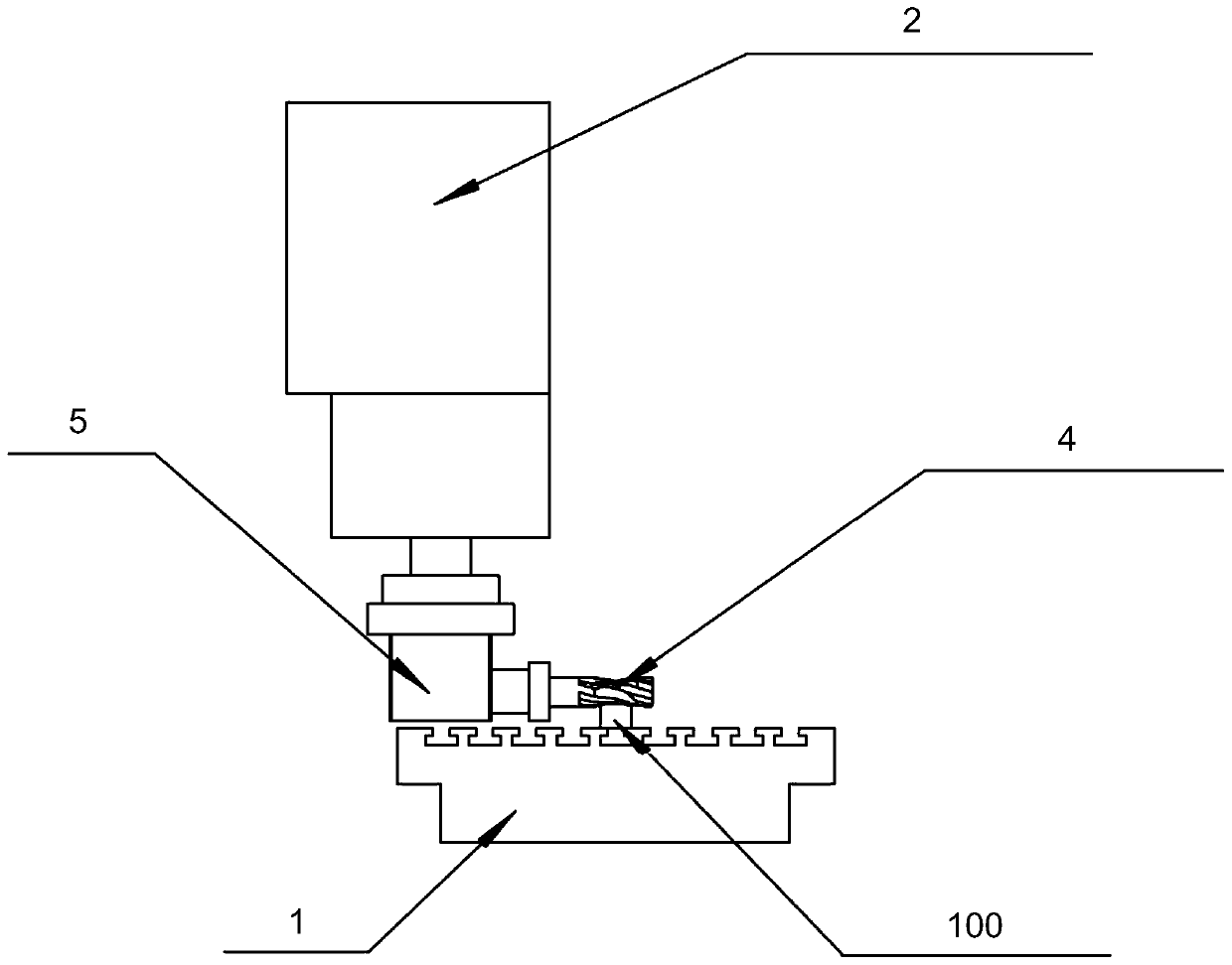
[0038] Please combine Figure 2 to Figure 11 As shown, a manufacturing system for heat transfer tube support bars for direct current steam generators of electric power equipment provided by the present invention includes a workbench 1 for placing heat transfer tube support bars 100, and a machining center spindle system 2 installed above the workbench 1 , connected to the tool at the lower end of the spindle system 2 of the machining center.

[0039] The cutting tool is the arc groove processing ...


PUM


Abstract

The invention discloses a manufacturing system of a heat transfer pipe support strip on a direct current steam generator of electric equipment. The manufacturing system comprises a workbench used forcontaining a heat transfer pipe support strip, a machining center main shaft system arranged above the workbench and a cutter connected to the lower end of the machining center main shaft system. Themanufacturing system further comprises a hoisting transfer device. The manufacturing system realizes the professional preparation production of the heat transfer pipe support strip.

Description

technical field [0001] The invention relates to a manufacturing system for a support bar of a heat transfer tube, in particular to a manufacturing system for a support bar of a heat transfer tube for a DC steam generator of electric equipment. Background technique [0002] Offshore floating power equipment is a distributed marine integrated energy system developed to meet safety requirements and marine user needs based on mature large-scale land-based commercial power equipment as a reference and combined with mature marine facility technology. Offshore floating power equipment is an important way to completely solve the problem of stable energy supply in China's coastal waters, distant seas, islands and reefs. With the emphasis on the marine economy, offshore floating power equipment has become a research and development hotspot in countries all over the world. As an energy supply system for marine applications, offshore floating power equipment has high efficiency, stabili...

Claims


Application Information

Patent Timeline
Patent Type & Authority Applications(China)
IPC IPC(8): B23C3/00B23C9/00B23Q3/12
CPCB23C3/00B23C9/00B23Q3/12
Inventor 蔡青春马丙金邵尚军周其成
Owner 上海瑞纽机械股份有限公司
Learn More