A charging pile with automatic one-way take-up

A charging pile, one-way technology, applied in the direction of electric vehicle charging technology, charging stations, electric vehicles, etc., can solve the problems that the charging gun cannot be automatically retracted, the charging line drags the floor, and is damaged, so as to prevent reverse rotation and prevent The effect of mopping the floor and protecting the motor

Active Publication Date: 2020-06-23
CHANGZHOU INST OF DALIAN UNIV OF TECH
View PDF8 Cites 0 Cited by
  • Summary
  • Abstract
  • Description
  • Claims
  • Application Information

AI Technical Summary

Problems solved by technology

[0004] The purpose of the present invention is to provide an automatic one-way charging pile to solve the problem that some users do not place the charging gun after using the existing charging pile with a charging gun in the background technology. In the correct position, the charging gun cannot automatically take up the wire, causing the charging wire to drag the floor and easily cause damage

Method used


Image

  • A charging pile with automatic one-way take-up
  • A charging pile with automatic one-way take-up
  • A charging pile with automatic one-way take-up

Examples


Embodiment 1

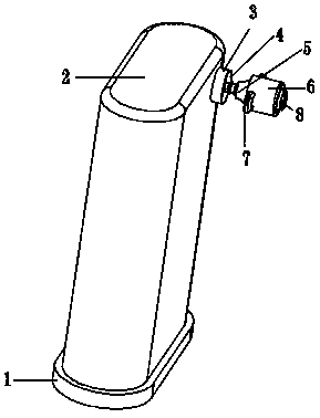
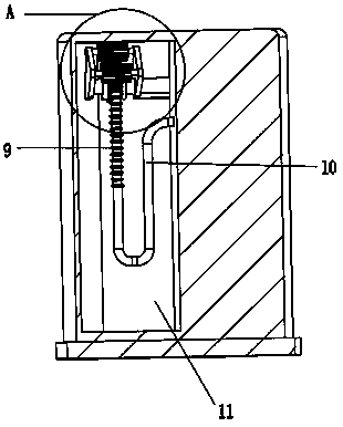
[0025] A specific application of this embodiment is: the present invention is connected to the charging device through the connecting long tube 10. When the user uses the charging gun, the charging gun 6 is pulled out by manually operating the handle 7. After use, the motor is started by controlling 13. The protruding connecting long tube 10 can be recovered through the engagement of the protrusion 9 and the stop tooth 25, and the connecting long tube 10 can be recovered, and the recovery of the connecting long tube 10 can be limited by the action of the two sets of movable tubes 20. To prevent the long connection tube 10 in the cavity 11 from twisting, the charging gun 6 can be accurately stuck on the gun outlet 3 through the cooperation of the arc surface 4 and the arc end surface 5, which facilitates the fixing of the charging gun 6 .

Embodiment 2

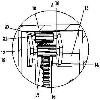
[0026] Embodiment 2: When the motor 13 rotates, the motor 13 drives the main shaft 16 and the outer disk 15 of the main shaft to rotate, and the main shaft 16 drives the cross turntable 22 to rotate, and the rotation of the cross turntable 22 generates centrifugal force so that the cylindrical column 24 is thrown toward The narrow side of the notch groove 26, through the extrusion effect of the cylindrical column 24, makes the cross turntable 22 drive the outer shell 17 to rotate, and through the engagement of the protrusion 9 and the stop tooth 25, the long connecting pipe 10 is recovered. When the long connecting pipe is pulled out manually At 10 o'clock, drive the casing 17 to rotate, extrude the cylinder column 24, so that the cylinder column 24 can overcome the elastic force of the spring 23 and enter the wide side of the notch groove 26, without driving the cross turntable 22 to rotate, and protect the motor 13. This device can realize automatic Take up the line to preven...


PUM


Abstract

The invention discloses an automatic one-way take-up charging pile which comprises a charging pile. A charging pile bottom plate is fixedly mounted at the bottom of the charging pile. A left inner cavity of the charging pile is provided with a cavity. A connecting long pipe is arranged in the cavity. The other end of the connecting long pipe is connected with a charging gun. The charging gun is positioned at the outer end of the charging pile. Two groups of mounting plates are fixedly mounted on the inner wall of the cavity, and two groups of movable shafts are fixedly mounted on the mountingplates. Movable cylinders are movably mounted on the outer walls of the movable shafts. A gun outlet is fixedly formed in the outer wall of the charging pile, and the connecting long pipe penetrates through the gun outlet. A charging jack is fixedly mounted on the outer wall of the charging gun. A plurality of groups of bulges are fixedly mounted on the outer wall of the connecting long pipe. A main rotating shaft is fixedly installed on the outer wall of the right group of mounting plate, and a main rotating shaft outer disc is movably installed on the outer wall of the main rotating shaft. According to the device, automatic take-up can be achieved, a charging wire is prevented from mopping the ground, the charging device is prevented from being damaged, and when the charging wire is pulled, a motor is protected, and a motor shaft is prevented from rotating reversely.

Description

technical field [0001] The invention relates to the technical field of charging piles, in particular to a charging pile with automatic one-way wire take-up. Background technique [0002] During the use of existing charging piles with charging guns, some users do not place the charging guns in the correct position after use, and the charging guns cannot automatically take up the wires, causing the charging wires to drag on the floor and easily causing damage. [0003] Based on this, the present invention designs an automatic one-way charging pile to solve the above problems. Contents of the invention [0004] The purpose of the present invention is to provide an automatic one-way charging pile to solve the problem that some users do not place the charging gun after using the existing charging pile with a charging gun in the background technology. In the correct position, the charging gun cannot automatically take up the wire, causing the charging wire to drag the floor and...

Claims


Application Information

Patent Timeline
Patent Type & Authority Patents(China)
IPC IPC(8): B60L53/31B65H75/38B65H75/44
CPCB60L53/31B65H75/38B65H75/4486B65H2701/34Y02T10/70Y02T10/7072Y02T90/12
Inventor 李强邹瑞洵
Owner CHANGZHOU INST OF DALIAN UNIV OF TECH
Why Eureka
Try Eureka