Fixed shaft type full-moving rudder surface mounting structure

An installation structure, fixed-axis technology, applied in transportation and packaging, aircraft parts, aircraft control, etc., can solve the problem of aircraft flutter speed and flight quality affecting the life of structural parts, increased rudder surface rotational friction, and rudder surface control. Clearance nonlinearity and other problems, to achieve the beneficial effects of aircraft flutter speed and flight quality, good installation consistency, and stable control clearance of the rudder surface

Active Publication Date: 2020-04-10
JIANGXI HONGDU AVIATION IND GRP
View PDF8 Cites 1 Cited by
  • Summary
  • Abstract
  • Description
  • Claims
  • Application Information

AI Technical Summary

Problems solved by technology

If the constraints and limits of each installation point are complicated and the constraints and limits are not clear, on the one hand, it will lead to poor assembly process, complicated installation steps, and poor installation consistency; in addition, if the installation structure is over-constrained, it will also cause rotational friction on the rudder surface Increased force, non-linear rudder surface control clearance, etc., affect the life of related structural parts, aircraft flutter speed and flight quality, etc.

Method used


Image

  • Fixed shaft type full-moving rudder surface mounting structure
  • Fixed shaft type full-moving rudder surface mounting structure
  • Fixed shaft type full-moving rudder surface mounting structure

Examples


Embodiment Construction

[0022] The embodiments will be described in detail below in conjunction with the accompanying drawings.

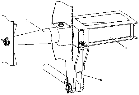
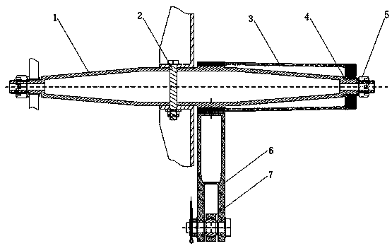
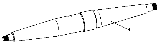
[0023] figure 1 It is a schematic diagram of the installation structure of the fixed-axis full-motion rudder surface, figure 2 for figure 1 sectional view of image 3 A schematic diagram of the shaft structure. See attached figure 1 To attach image 3 , the installation structure of the fixed-axis full-motion rudder surface includes a rotating shaft 1, a beam 3 and a rocker arm 6, the rotating shaft 1 is fixed on the supporting structure, the beam 3 is sleeved on the rotating shaft 1 and locked, and the rocking arm 6 is fixed On the beam 3, the steering gear 7 operates the rocker arm 6 to drive the beam 3 to rotate around the rotating shaft 1, and the beam 3 is set on the rotating shaft 1 as a double fulcrum.

[0024] Considering that the rotating shaft 1 and the rudder surface are generally supported by double fulcrums, the fulcrum load of the fuselage section clos...


PUM


Abstract

A fixed shaft type full-moving rudder surface mounting structure provided by the invention comprises a rotating shaft, a limiting bolt, a beam, a cushion block, a tightening nut and a rocker arm, andthe rotating shaft is inserted into a fuselage supporting structure and is fixed through the limiting bolt. The beam and the cushion block are sleeved on the rotating shaft and are locked by the tightening nut combined with the rotating shaft, the rocker arm is fixedly connected with the beam through bolts, and a steering engine controls the rocker arm to drive the beam to rotate around the rotating shaft. The fixed shaft type full-moving rudder surface mounting structure has the characteristics of only one key mounting procedure, simple limiting structure and limiting mode, clear limiting effect of each fulcrum, no over-constraint, effectiveness in guaranteeing that the installation position of the full-moving rudder surface is within the reasonable tolerance range relative to the theoretical position of the full-moving rudder surface, stable rudder surface control gap, no increase of the rotating friction force of the rudder surface, and facilitation of improvement of the service life of related structural parts, the airplane flutter speed and the flight quality.

Description

technical field [0001] The invention belongs to the technical field of aircraft structure design, and in particular relates to a fixed-axis type full-motion rudder surface installation structure. Background technique [0002] When the flight speed of the aircraft reaches supersonic flight, in order to improve the control efficiency of the rudder surface, the full motion rudder surface must be used. Full-motion rudder surfaces usually include full-motion horizontal tail, full-motion vertical tail, and full-motion canard. [0003] The installation structure of the full-motion rudder surface shall be determined according to the overall layout, structural space, assembly processability and maintainability, etc., to determine the axial radial and torsional limit constraints of the rotating shaft, as well as the limit constraints of the rudder surface, so as to ensure that the full-motion rudder The mounting position of the surface is within reasonable tolerances relative to its ...

Claims


Application Information

Patent Timeline
Patent Type & Authority Applications(China)
IPC IPC(8): B64C9/02
CPCB64C9/02Y02T50/40
Inventor 夏彦朋王建华黄鑫吴畏张华文永洪冷旻衠张玉华
Owner JIANGXI HONGDU AVIATION IND GRP
Why Eureka
Try Eureka