
Helicopter rotor blade based on seamless trailing edge flap mechanism

A technology for helicopter rotors and trailing edge flaps, applied in the directions of rotorcraft, motor vehicles, aircraft, etc., can solve the problems of high blade ground clearance, reduced aerodynamic efficiency of trailing edge flaps, inconvenient maintenance and repair, etc. The effect of improving the aerodynamic efficiency, improving the practical value of the project, and reducing the workload of system maintenance

Pending Publication Date: 2020-04-10
NANJING UNIV OF AERONAUTICS & ASTRONAUTICS
View PDF0 Cites 6 Cited by
  • Summary
  • Abstract
  • Description
  • Claims
  • Application Information

AI Technical Summary

Problems solved by technology

However, during the use of the helicopter, its vibration and noise problems have always been prominent, which has brought a negative impact on the further development of the helicopter
[0004] The trailing edge flap needs to deflect and move relative to the blade body. The existing trailing edge flap design mostly adopts the traditional hinge mechanism. There is inevitably a chord gap between the trailing edge flap and the blade body, and the flow through the blade The airflow on the upper and lower surfaces will pass through the chord gap, reducing the aerodynamic efficiency of the trailing edge flap
In addition, in the existing trailing-edge flap design, the trailing-edge flap and the driving mechanism are separately connected to the blade body, and the inspection and maintenance of the mechanism are realized through the flaps arranged on the upper or lower surface of the blade. On the one hand, the existence of the flap changes the aerodynamic shape of the blade. On the other hand, due to the high ground clearance of the blade, the trailing edge flap and the driving mechanism directly installed and fixed on the blade body bring difficulties to the daily inspection and maintenance work. inconvenient

Method used


Image

  • Helicopter rotor blade based on seamless trailing edge flap mechanism
  • Helicopter rotor blade based on seamless trailing edge flap mechanism
  • Helicopter rotor blade based on seamless trailing edge flap mechanism

Examples


Embodiment Construction

[0033] Below in conjunction with accompanying drawing, technical scheme of the present invention is described in further detail:

[0034] This invention may be embodied in many different forms and should not be construed as limited to the embodiments set forth herein. Rather, these embodiments are provided so that this disclosure will be thorough and complete, and will fully convey the scope of the invention to those skilled in the art. In the drawings, components are exaggerated for clarity.

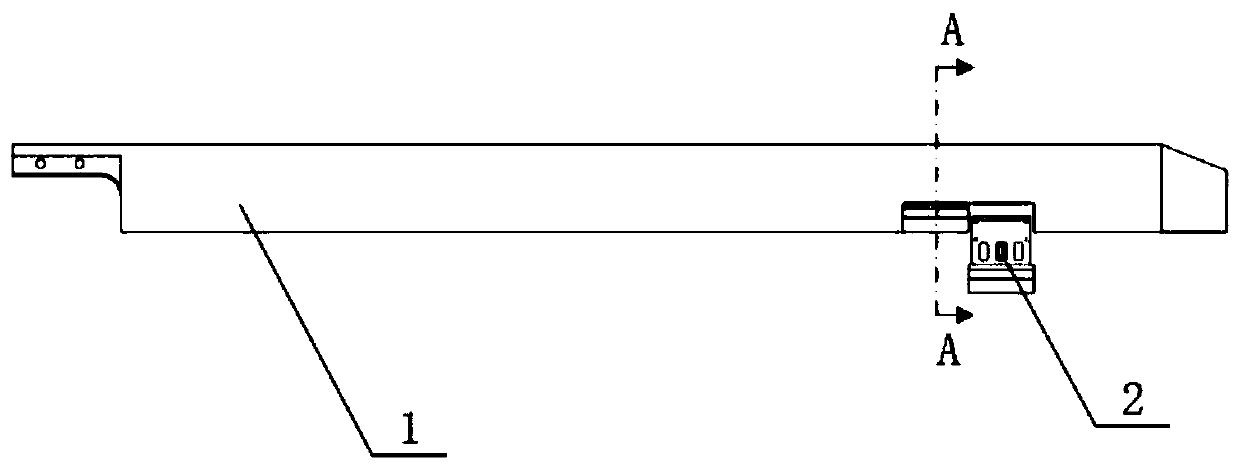
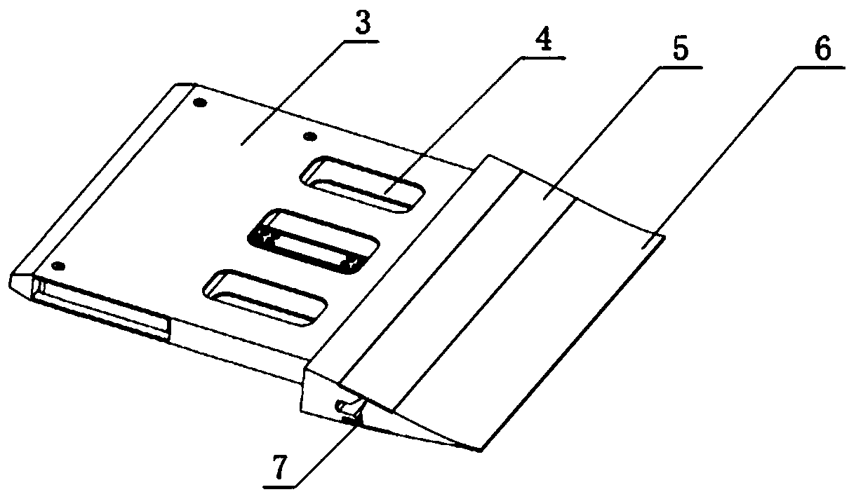
[0035] The invention discloses a helicopter rotor blade based on a seamless trailing edge flap mechanism, which comprises a blade body and several trailing edge flap modules;

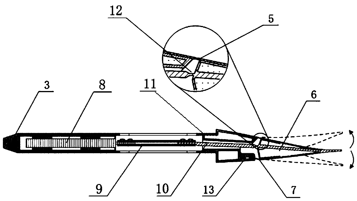
[0036] Such as figure 2 , image 3 As shown, the trailing edge flap module includes a housing, a driver, a push-pull rod, a driving rod, an installation platform, a first flexible hinge, a second flexible hinge, a trailing edge flap and a sealing sheet;

[0037] Such as Figure 6 As shown, the housing is a ...


PUM


Abstract

The invention discloses a helicopter rotor blade based on a seamless trailing edge flap mechanism. The helicopter rotor blade comprises a blade body and a plurality of trailing edge flap modules, wherein the trailing edge flap module comprises a shell, a driver, a push-pull rod, a driving rod, a mounting platform, a first flexible hinge, a second flexible hinge, a trailing edge flap and a sealingpiece; the driver generates dynamic linear displacement output; the driver, the push-pull rod, the driving rod and the trailing edge flap are connected in sequence, and the force and displacement generated by the driver are output and transmitted to the trailing edge flap; and the trailing edge flap is connected with the mounting platform through the second flexible hinge, and the linear reciprocating motion of the push-pull rod is converted into the deflection motion of the trailing edge flap through the second flexible hinge. The helicopter rotor blade is applied to the trailing edge flaps of the helicopter to actively control a rotor wing, the aerodynamic load distribution of the blade is dynamically changed through dynamic deflection of the trailing edge flaps, the vibration load of the rotor wing of the helicopter is inhibited, or the noise of the rotor wing is inhibited through a sound field cancellation method.

Description

technical field [0001] The invention relates to the field of active control of helicopter rotor vibration and noise, in particular to a helicopter rotor blade based on a seamless trailing edge flap mechanism. Background technique [0002] Compared with other types of aircraft, helicopters have the characteristics of vertical take-off and landing and efficient hovering, and have been widely used in civil and military fields. However, during the use of the helicopter, its vibration and noise problems have always been prominent, which has brought a negative impact on the further development of the helicopter. When the helicopter is flying forward, the rotor is in an asymmetric and complex working environment. The shock wave of the forward blade, the dynamic stall of the backward blade, and the regurgitation zone cause the rotor to generate strong vibration and noise. Strong vibration and noise problems not only affect the comfort of helicopter pilots, but also adversely affect...

Claims


Application Information

Patent Timeline
Patent Type & Authority Applications(China)
IPC IPC(8): B64C27/46B64C27/467B64C27/51
CPCB64C27/46B64C27/467B64C27/51
Inventor 杨卫东周金龙董凌华
Owner NANJING UNIV OF AERONAUTICS & ASTRONAUTICS
Learn More