Plate part storage device and storage and taking method thereof

A storage device and access method technology, applied in packaging, internal accessories, transportation and packaging, etc., can solve the problems of increased production costs, cumbersome operations, and large storage space, and achieve the effect of strong adaptability

Active Publication Date: 2020-04-10
哈工大机器人南昌智能制造研究院
View PDF9 Cites 0 Cited by
  • Summary
  • Abstract
  • Description
  • Claims
  • Application Information

AI Technical Summary

Problems solved by technology

[0002] In some technical fields of automated welding, since automated welding is carried out in batches according to project orders, a variety of plate parts of different specifications will be produced, while parts of the same specification are stacked and stacked horizontally. This requires a lot of storage space, resulting in a waste of space; during welding production and processing, generally use a transfer robot with a suction tool to absorb and transfer plate parts, and then send them to the welding robot for welding; and because most of the parts are horizontal Overlapping, so when the robot picks up, it needs to use a special auxiliary mechanism to adjust the position or flip the direction, which is very cumbersome
And because the board parts are placed flat, and the working range of the transfer robot is limited, and the size of the board parts varies, then the same transfer robot can only place a small number of types of board parts in the working range, so that Multiple transfer robots are required to work simultaneously to increase work coverage and meet the transfer of various types of plate parts, resulting in increased production costs

Method used


Image

  • Plate part storage device and storage and taking method thereof
  • Plate part storage device and storage and taking method thereof
  • Plate part storage device and storage and taking method thereof

Examples


Embodiment Construction

[0025] The present invention will be described in further detail below through specific examples.

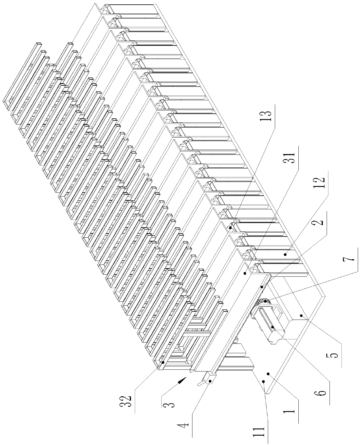
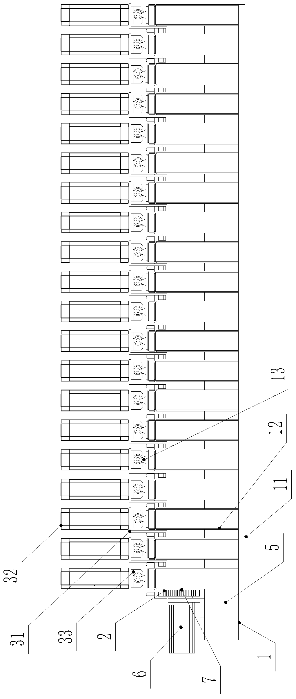
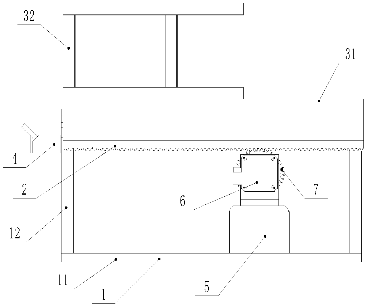
[0026] Such as Figure 1 to Figure 3 As shown, a storage device for plate parts includes a base 1 on which several storage frames 3 for placing upright plate parts are installed, and the storage frames 3 are arranged along the length direction of the base 1, Arranged at intervals, each storage frame 3 has the same structure.

[0027] Wherein said base 1 comprises an installation base plate 11 and several support frames 12 arranged at equal intervals arranged on the installation base plate 11, the top of each support frame 12 is provided with a transverse guide rail 13, and each storage base plate 31 is slidably installed on On the corresponding transverse guide rail 13, the support frame 12 is welded into a structure similar to a rectangular frame by adopting rectangular profiles, and the bottom of the support frame 12 is welded or bolted to the installation point.

[0028] Ea...


PUM


Abstract

The invention discloses a plate part storage device, which comprises a base. Storage frames are installed on the base. The storage frames are arranged at equal intervals in the length direction of thebase. The structures of the storage frames are the same. Each storage frame comprises a storage bottom plate sliding in the width direction of the base. A surrounding frame used for supporting vertical plate parts is arranged above the storage bottom plate. An upper placing opening and a side placing opening are formed in the upper portion of the surrounding frame and one side of the surroundingframe in the width direction respectively, and a linear driving mechanism for driving any storage frame to slide in the width direction is arranged on the base. The storage device vertically places the plate parts, and meanwhile material storing and taking of a transfer robot are facilitated. In addition, the invention further discloses a plate part storing and taking method using the storage device, the storage device is used in the storage and taking method, the plate parts can be vertically stored or taken out, and material storing and taking of the transfer robot are facilitated.

Description

technical field [0001] The invention relates to a storage device for plate parts, and also relates to an access method using the storage device, which is suitable for some automatic welding technical fields. Background technique [0002] In some technical fields of automated welding, since automated welding is carried out in batches according to project orders, a variety of plate parts of different specifications will be produced, while parts of the same specification are stacked and stacked horizontally. This requires a lot of storage space, resulting in a waste of space; during welding production and processing, generally use a transfer robot with a suction tool to absorb and transfer plate parts, and then send them to the welding robot for welding; and because most of the parts are horizontal Overlapping, so when the robot is picking up, it needs to use a special auxiliary mechanism to adjust the position or flip the direction, which is very cumbersome. And because the b...

Claims


Application Information

Patent Timeline
Patent Type & Authority Applications(China)
IPC IPC(8): B65D25/02B65D6/08
CPCB65D25/02B65D7/14
Inventor 赵亮丰俊奇
Owner 哈工大机器人南昌智能制造研究院
Why Eureka
Try Eureka