Drill-holding-prevention electric control system for power head and control method thereof and rotary drilling rig

An electric control system and control method technology, applied in the direction of drilling automatic control system, rotary drilling rig, drilling equipment and method, etc., can solve the problems of damaging the service life of the power head motor and affecting the driving efficiency of equipment construction, etc., to prevent Drilling phenomenon, simple installation, and the effect of ensuring efficiency

Active Publication Date: 2020-04-10
SHANGHAI ZOOMLION HEAVY IND PILING MACHINERYCO
View PDF5 Cites 3 Cited by
  • Summary
  • Abstract
  • Description
  • Claims
  • Application Information

AI Technical Summary

Problems solved by technology

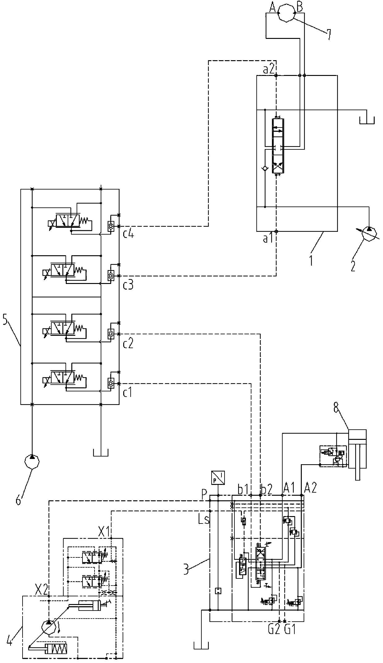
[0004] In the case of hard rock formations, if the pressure applied to the power head by the pressurized cylinder 8 is too large, the load torque on the power head will increase accordingly. When the load torque is close to the maximum power head motor 7 When torque is applied, affected by the friction of the underground rock formation, the drill bit may not be able to rotate, and the power head motor 7 stops rotating, which will form a phenomenon of "drilling". At this time, the operator needs to manually cancel or reduce the pressure of the pressurized cylinder 8 (Manual pressure relief), frequent drilling will affect the actual construction and excavation efficiency of the equipment, and in severe cases will damage the service life of the power head motor

Method used


Image

  • Drill-holding-prevention electric control system for power head and control method thereof and rotary drilling rig
  • Drill-holding-prevention electric control system for power head and control method thereof and rotary drilling rig
  • Drill-holding-prevention electric control system for power head and control method thereof and rotary drilling rig

Examples


Embodiment Construction

[0047] Specific embodiments of the present invention will be described in detail below in conjunction with the accompanying drawings. It should be understood that the specific embodiments described here are only used to illustrate and explain the present invention, and are not intended to limit the present invention.

[0048] In addition, the terms "first", "second", "third", "fourth", "fifth", "sixth", "seventh" are used for descriptive purposes only and should not be construed as indicative or implying relative importance or implicitly specifying the number of technical features indicated, thus qualifying "first", "second", "third", "fourth", "fifth", "sixth", The "seventh" feature may explicitly or implicitly include one or more of said features.

[0049] In the description of the present invention, it should be noted that unless otherwise specified and limited, the terms "setting" and "connection" should be understood in a broad sense, for example, it can be a fixed conne...


PUM


Abstract

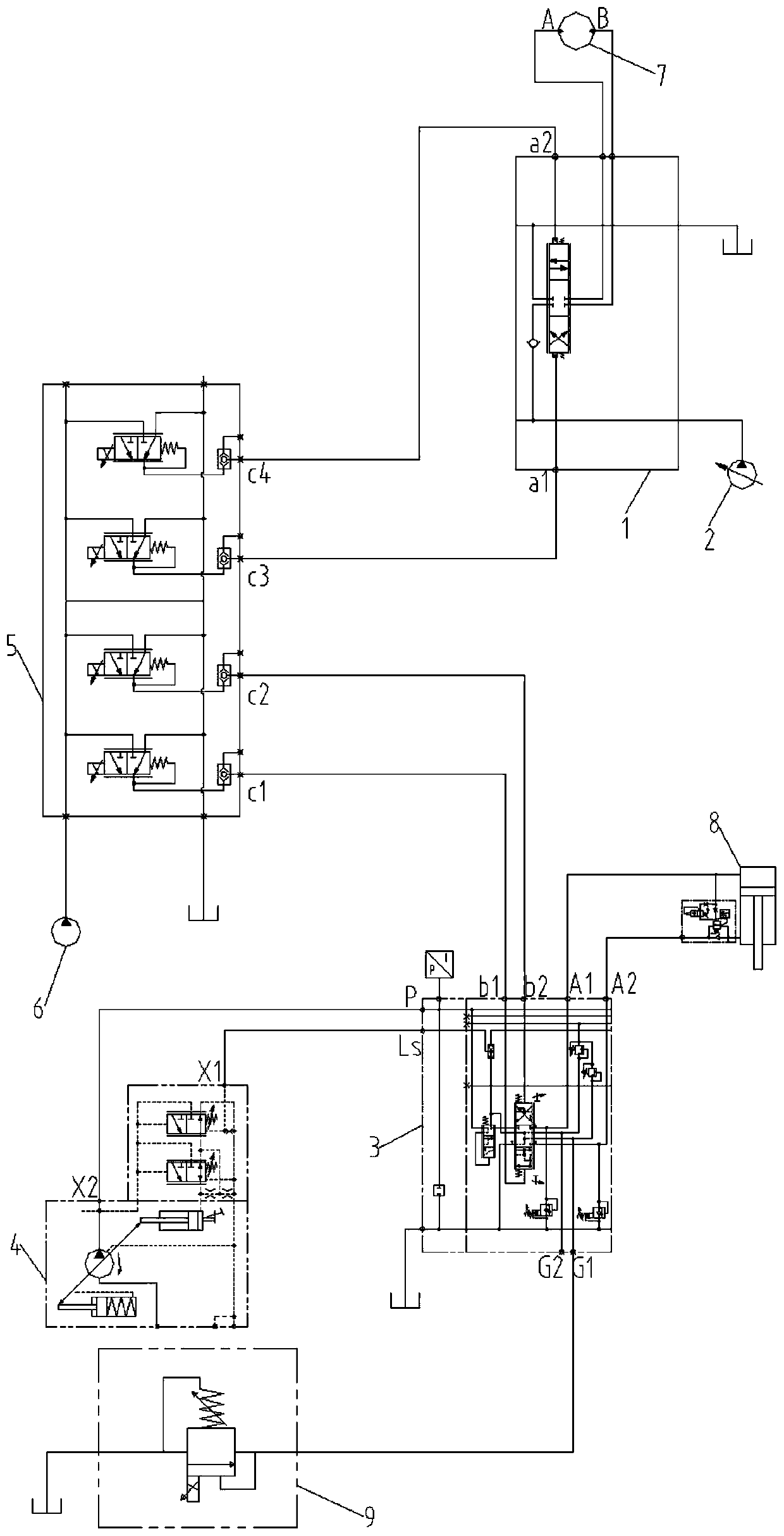
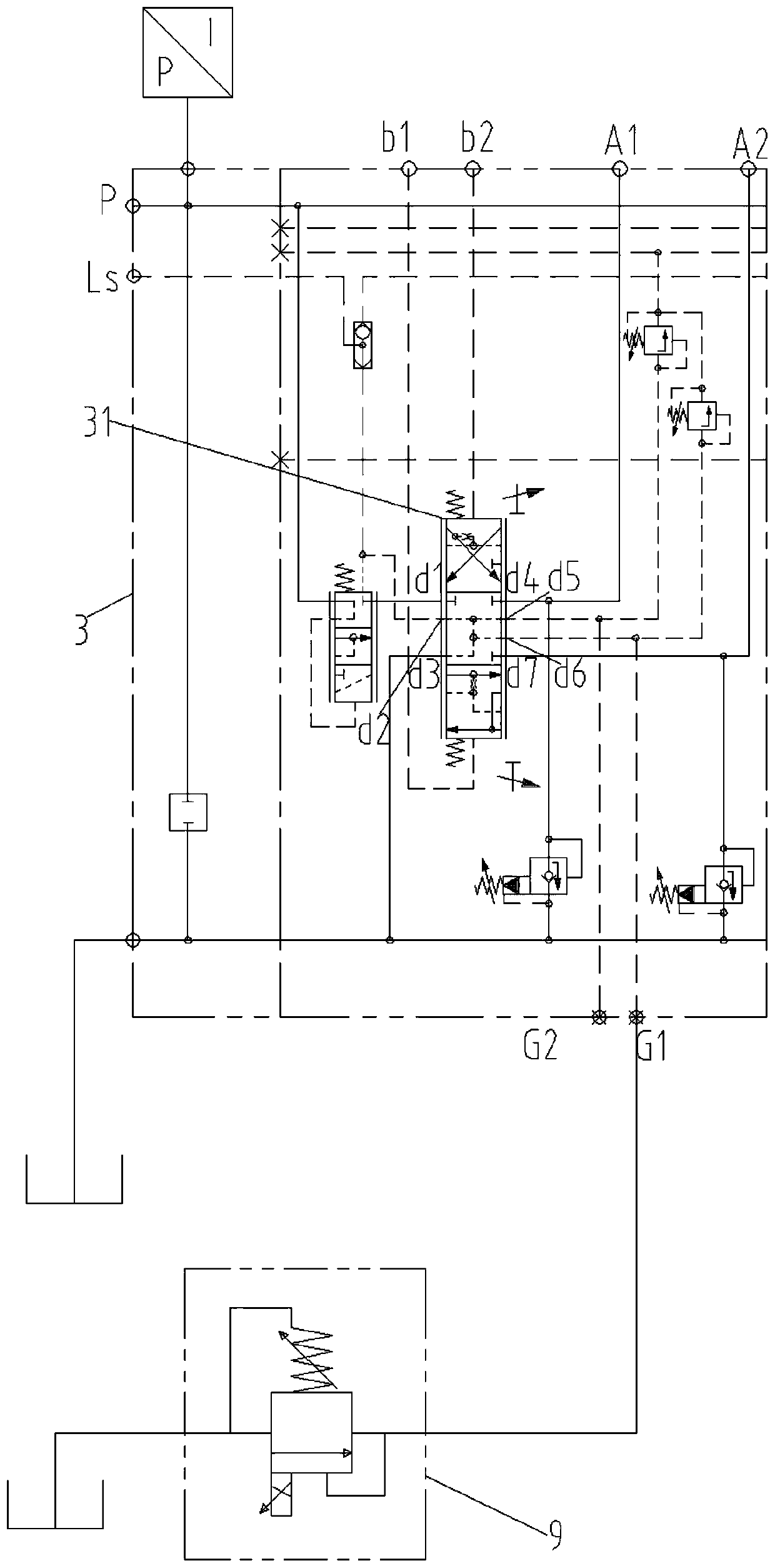
The invention discloses a drill-holding-prevention electric control system for a power head. The system comprises a main valve, a main pump, an auxiliary valve, an auxiliary pump and a pilot valve connected with a pilot pump, wherein the main pump is connected with a power head motor through the main valve; the auxiliary pump is connected with a pressurizing oil cylinder through the auxiliary valve; and the main valve and the auxiliary valve are further connected with the pilot valve so that reversing of the main valve and the auxiliary valve can be controlled through the pilot valve. The system further comprises a controller and a flow control valve electrically connected with the controller; the power head motor is provided with a rotating speed detection device which is electrically connected with the controller and used for detecting the rotating speed of a power head; one end of the flow control valve is connected with an auxiliary valve feedback oil port through a reversing valvein the auxiliary valve, and the other end of the flow control valve is connected with an oil tank; and the controller can control the opening degree of a valve port of the flow control valve according to feedback information of the rotating speed detection device so that the pressurizing force of the pressurizing oil cylinder can be reduced. The invention further discloses a control method of thedrill-holding-prevention electric control system and a rotary drilling rig. With the adoption of the method, drill holding can be prevented.

Description

technical field [0001] The present invention relates to a hydraulic control system of a drilling rig, in particular to an electric control system for anti-squeeze drilling of a power head. A rotary drilling rig. Background technique [0002] Rotary drilling rig is a construction machine suitable for hole-forming operations in building foundation engineering. It is mainly suitable for the construction of sandy soil, cohesive soil, silty soil and other soil layers. It is widely used in various foundation constructions such as cast-in-situ piles, diaphragm walls, and foundation reinforcement. Mast, telescopic drill pipe, with vertical automatic detection and adjustment, digital display of hole depth, etc. The operation of the whole machine generally adopts hydraulic pilot control and load sensing, which has the characteristics of light and comfortable operation. [0003] figure 1 It shows a power head hydraulic system in the prior art. After the drill bucket is lowered to th...

Claims


Application Information

Patent Timeline
Patent Type & Authority Applications(China)
IPC IPC(8): E21B44/00E21B3/02
CPCE21B44/00E21B3/02
Inventor 黄建林何欢
Owner SHANGHAI ZOOMLION HEAVY IND PILING MACHINERYCO
Why Eureka
Try Eureka