Different-shaft acceleration turbocharger

A turbocharger and different shaft technology, applied in the direction of machines/engines, engine components, internal combustion piston engines, etc., can solve the problems of limiting the speed of the compressor end and the speed cannot reach a higher speed, so as to reduce turbo hysteresis and improve fuel economy , the effect of reducing emissions

Pending Publication Date: 2020-04-10
郏政广
View PDF0 Cites 1 Cited by
  • Summary
  • Abstract
  • Description
  • Claims
  • Application Information

AI Technical Summary

Problems solved by technology

[0003] As a result, the speed of the turbocharger blades cannot reach a higher speed. The pump gas and compressor turbines in the existing technology are coaxially connected, thus limiting the speed of the compressor end.

Method used


Image

  • Different-shaft acceleration turbocharger
  • Different-shaft acceleration turbocharger

Examples


Embodiment Construction

[0018] The present invention will be described below with reference to specific examples. Those skilled in the art can understand that these examples are only for illustrating the present invention, and they do not limit the scope of the present invention in any way.

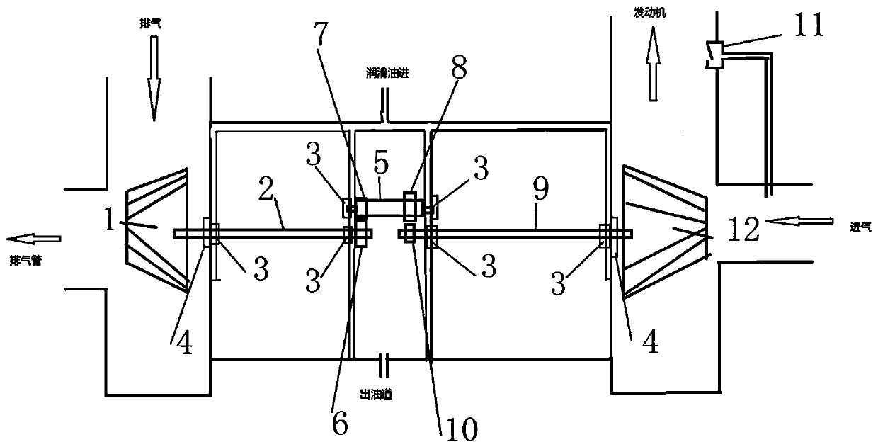
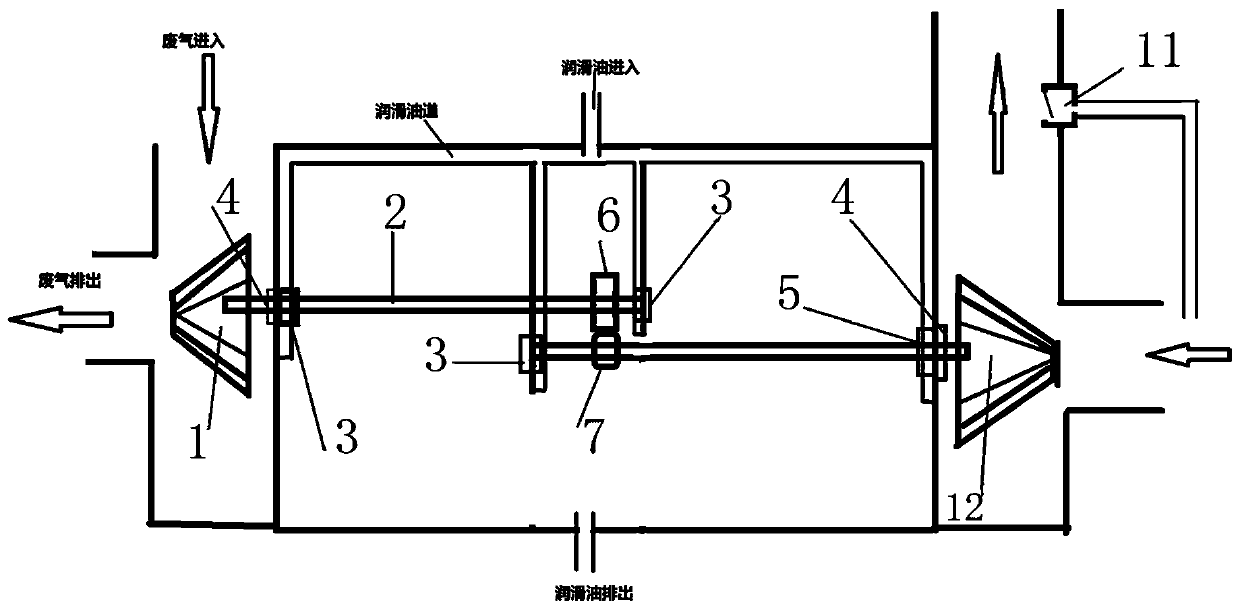
[0019] A counter-shaft turbocharger, such as figure 1 with figure 2 As shown, it includes the pump impeller (1), the compressor impeller (12), the driving shaft (2), the driven shaft (5) and the final shaft (9); the right end of the pump impeller (1) is fixedly connected with the driving shaft (2 ); floating bearings (3) are respectively fixed on the inner sides of both ends of the driving shaft (2); a thrust bearing (4) is fixed on the outer side of the connecting end of the driving shaft (2) and the pump impeller (1); the right side of the driving shaft (2) The driving gear (6) is fixed at the end;

[0020] The drive shaft (2) is provided with a final shaft (9) on the right end of the same horizontal plane...


PUM


Abstract

The invention provides a different-shaft acceleration turbocharger comprising an air pumping impeller, an air compression impeller, a driving shaft, a driven shaft and a final shaft. The air pumping impeller drives the driving shaft at the right end to rotate. A floating bearing and a thrust bearing are fixed to the two ends of the driving shaft. A driving gear is fixed to the right end. One finalshaft is arranged at the right end of the same horizontal plane of the driving shaft. A floating bearing and a thrust bearing are fixed to the two ends of the final shaft, and a final shaft gear is fixed to the left end. The air compression impeller is connected to the right end of the final shaft. The driven shaft is fixed to the right end of the driving shaft and the upper portion of the left end of the final shaft. Floating bearings are fixed to the two ends of the driven shaft, and a first driven gear and a second driven gear are installed on the inner sides of the two ends correspondingly. The first driven gear and the driving gear are in meshed connection. The second driving gear and the final shaft gear are in meshed connection. A gear transmission mode is adopted, the rotation speed is adjusted according to an engine and through the characteristics of the turbocharger, and best operation of the engine is achieved.

Description

technical field [0001] The invention relates to a supercharger, in particular to a turbocharger with different shaft speed increasing. Background technique [0002] The existing turbocharger responds slowly to the sudden change of the throttle. When the engine is at low speed or idling, the turbocharger blades are limited by the exhaust impact frequency, and the speed is not enough to provide sufficient intake pressure. On the contrary, the turbine blades at the compressor end It becomes an air intake obstruction during rapid acceleration, causing turbo lag and an abrupt driving experience. And it will be difficult to master for ordinary driving, driving difficulty and even potential safety hazard. Because the vane turbocharger determines the compressed air volume by the high-speed extrusion of the compressor blades, the higher the speed, the greater the pressure. When the engine is at low speed or idling, the engine exhaust gas is limited by the exhaust impact frequency, ...

Claims


Application Information

Patent Timeline
Patent Type & Authority Applications(China)
IPC IPC(8): F02B37/12F02B39/14
CPCF02B37/12F02B39/14F02B2037/122Y02T10/12
Inventor 郏政广
Owner 郏政广
Why Eureka
Try Eureka