Eureka AIR delivers breakthrough ideas for toughest innovation challenges, trusted by R&D personnel around the world.

Solid rocket engine case belt drive continuous filling pouring device and process

An engine casing and solid rocket technology, which is applied to rocket engine devices, machines/engines, mechanical equipment, etc., can solve the problems of increasing demand for small solid rocket engines, many types of auxiliary supporting systems, and poor slurry flow control accuracy. To achieve the effect of simplifying the complex work mode, reducing the amount of residual slurry, and reducing the cost of civil engineering

Pending Publication Date: 2020-04-10
HUBEI SANJIANG AEROSPACE JIANGHE CHEM TECH
View PDF6 Cites 2 Cited by
  • Summary
  • Abstract
  • Description
  • Claims
  • Application Information

AI Technical Summary

Problems solved by technology

[0003] Since the slurry pouring needs to be carried out in a metal vacuum tank, it is necessary to frequently open the vacuum tank—into the shell—vacuumize—pouring—open the vacuum tank—out of the shell. The problems of poor quality reliability, high safety risks and low production efficiency are particularly prominent, and the entire vacuum pouring system has problems such as large equipment footprint, many types of auxiliary supporting systems, and poor slurry flow control accuracy.
With the development of science and technology, the demand for small solid rocket motors has increased significantly, and the existing production methods cannot meet the large demand

Method used


Image

  • Solid rocket engine case belt drive continuous filling pouring device and process
  • Solid rocket engine case belt drive continuous filling pouring device and process
  • Solid rocket engine case belt drive continuous filling pouring device and process

Examples


Embodiment 1

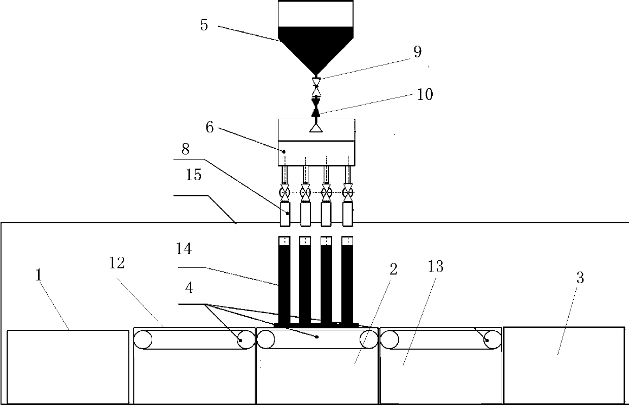
[0029] like Figure 2-4 As shown, a solid rocket motor casing belt drive continuous filling pouring equipment, including pouring preparation area 1, pouring area 2 and discharge area 3 arranged in sequence, between pouring preparation area 1, pouring area 2 and discharge area 3 Conveyor belts 4 are arranged in sequence; the primary hopper 5 is arranged above the conveyor belt in the pouring area, and the secondary hopper 6 is connected below the primary hopper. A reciprocating pump 7 is arranged on the pipeline between the head 8, the discharge port and the filling head. The filling head 8 cooperates with the engine casing 14 to realize pouring. The secondary hopper and the canning head are connected with a vacuum pipeline. Through the quantitative and metered feeding technology of reciprocating pumps, combined with the special requirements of dangerous cremation workplaces and the pouring process characteristics of solid rocket motor casings, an assembly line production opera...

Embodiment 2

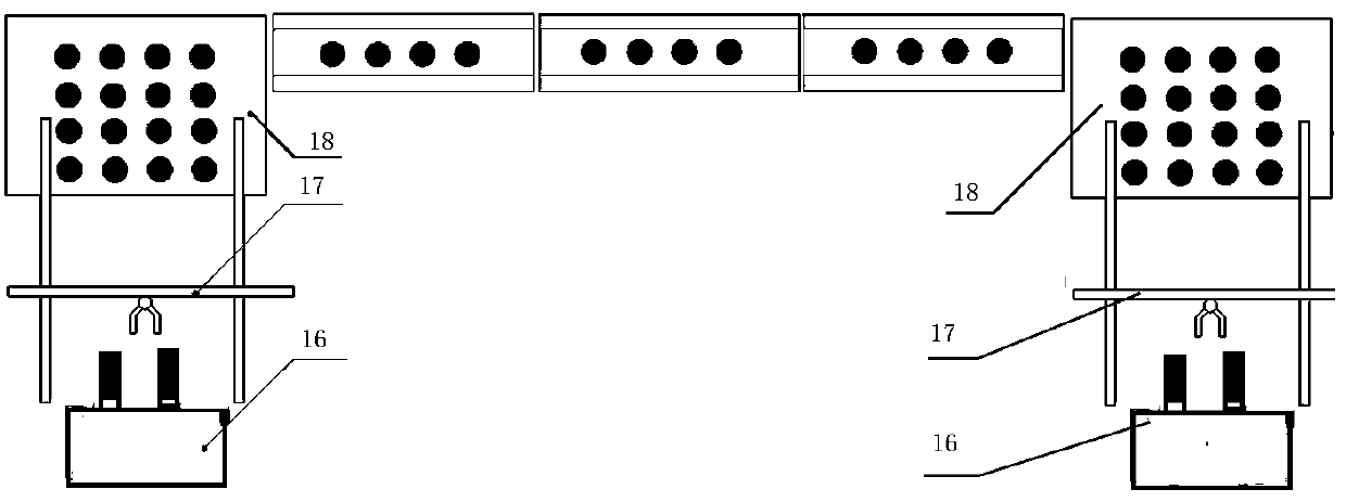
[0042]Carry out canned pouring for the engine casing with a specification of Ø200×XXXmm. During the specific operation, the process of transporting the engine casing (hereinafter referred to as the casing) to the pouring area, the working process is that the casing is packed with a set of brackets for 16 sets The AGV intelligent transfer vehicle (hereinafter referred to as AGV) is transferred from the warehouse to the truss manipulator position in the preparation area, and the truss manipulator grabs the upper shell of the AGV one by one and transfers it to the feeder. The feeder presses 4 shells one by one. The group pushes to the conveyor belt, and the conveyor belt transports the received shells to the waiting area, and then transports them to the pouring area when pouring is required. In the preparation stage, it is also necessary to prepare the mixed slurry. Specifically, the mixed slurry is transferred to the primary pouring hopper, and the primary hopper is hoisted to th...


PUM


Abstract

The invention discloses a solid rocket engine case belt drive continuous filling pouring device and process. The device comprises a pouring preparing area, a pouring area and a discharging area whichare arranged in sequence, a conveying belt is sequentially arranged among the pouring preparing area, the pouring area and the discharging area, a primary hopper is arranged above the conveying belt of the pouring area, a secondary hopper is connected to the lower portion of the primary hopper, the secondary hopper is provided with multiple discharging openings, the discharging openings are connected to a filling head through pipelines, reciprocating pumps are arranged on the pipelines between the discharging openings and the filling head, the filling head and an engine case are matched to achieve pouring, and the secondary hopper and the filling head are connected with a vacuum pipeline. Solid rocket engine pouring is changed into a production line mode, automatic filling is achieved, andproduction efficiency is improved.

Description

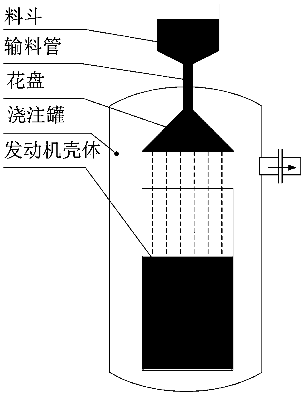
technical field [0001] The invention belongs to the field of pouring of solid rocket motor casings, and in particular relates to belt-driven continuous filling and pouring equipment and technology for solid rocket motor casings. Background technique [0002] The engine shell slurry pouring process is a very important process in the production process of solid rocket motors. It pours the qualified slurry into the engine shell by vacuum pouring, and after curing, it is made into a product that meets the design requirements. . The existing pouring is to install and fix the engine casing in the vacuum container (pouring tank) with hot water heating jacket on the outer wall, and pass the mixed slurry in the hopper through the delivery pipe under the condition that the container is completely in a vacuum environment. flow into the housing. In order to completely remove the gas entrained in the slurry in a vacuum environment, before the slurry enters the engine casing, the slurry...

Claims


Application Information

Patent Timeline
Patent Type & Authority Applications(China)
IPC IPC(8): F02K9/24
CPCF02K9/24
Inventor 崔峰李换朝邓安华吕磊张华燕华侨左江明曾广斌
Owner HUBEI SANJIANG AEROSPACE JIANGHE CHEM TECH
Why Eureka
Eureka Blog
Learn More