Ignition device suitable for end combustion grain and assembling method

A technology of an ignition device and an assembly method, which is applied to rocket engine devices, jet propulsion devices, machines/engines, etc., can solve the problems of difficulty in implementation and difficult to fix aluminum tubes, and achieves reduced charge loss, small space, and improved mass ratio. Effect

Inactive Publication Date: 2020-04-10
SHANGHAI XINLI POWER EQUIP RES INST
View PDF6 Cites 2 Cited by
  • Summary
  • Abstract
  • Description
  • Claims
  • Application Information

AI Technical Summary

Problems solved by technology

When the end-fired grain adopts the form of free filling, the bonding process of the top cover and the coated grain is after the powder is poured and solidified, and the coating sleeve is made of rubber. It is not easy to fix the aluminum tube by the above method of passing through the aluminum tube through the center. more difficult to achieve

Method used


Image

  • Ignition device suitable for end combustion grain and assembling method
  • Ignition device suitable for end combustion grain and assembling method

Examples


Embodiment 1

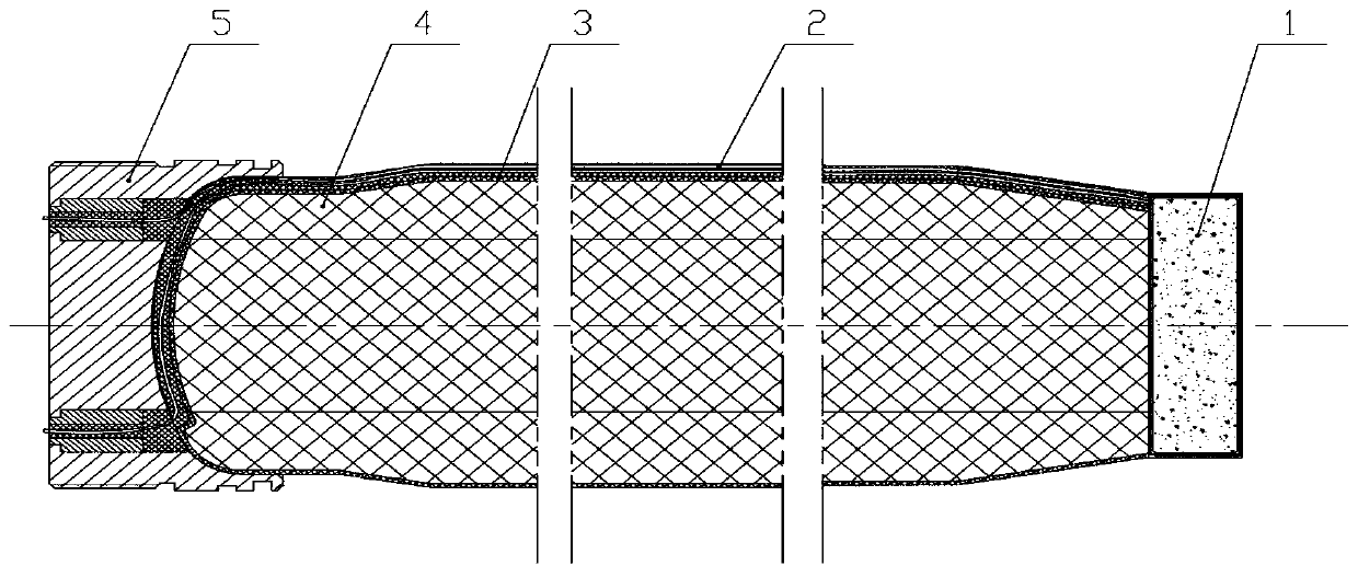
[0030] An ignition device suitable for an end-fired charge, comprising an ignition charge box 1, an ignition wire 2, a covering sleeve 3, a charge 4, and a top cover 5;

[0031] After the powder column 4 is bonded to the ignition powder box 1, the ignition powder box 1 is used as the head of the ignition device; the coating sleeve 3 is coated on the powder column 4; the top cover 5 and the After the covering sleeve 3 is bonded, the top cover 5 is used as the tail of the ignition device;

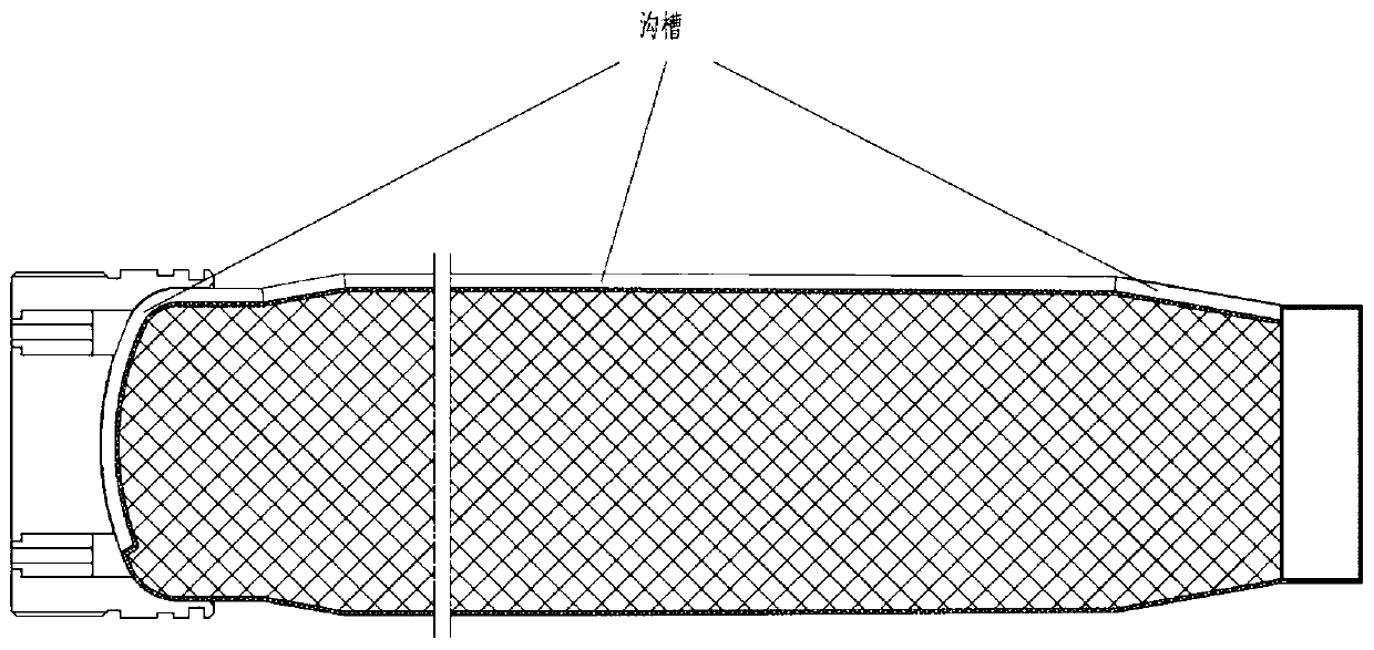
[0032] The outer surface of the covering sleeve 3 is provided with a groove, and the ignition wire 2 is installed in the groove; the top cover 5 is provided with a through hole, and one end of the ignition wire 2 is connected to the ignition cartridge 1 connection, and the other end passes through the through hole on the top cover 5.

[0033] The groove is semi-cylindrical, and after the ignition wire 2 is installed in the groove, the groove is filled with an adhesive, and finally the adhesi...

Embodiment 2

[0041] An ignition device suitable for end-combustion powder, wherein the method for the outlet of the ignition device adopts the method of wiring on the outer surface of the coating sleeve 3 of the free-filling powder; the outer surface of the coating sleeve 3 is provided with grooves; the The above-mentioned groove adopts special tooling to ensure its structural size; after the ignition wire 2 of the ignition device is arranged, the above-mentioned groove is completely filled and cured with adhesive, and local shaping is allowed to ensure that the assembly is not affected if necessary; The top cover 5 used in the outgoing line method is designed with an opening that cooperates with the ignition wire 2 through the cabin; the design of the opening structure of the top cover 5 should meet the sealing requirements.

[0042] figure 1 Shown is a schematic diagram of the structure of an ignition device suitable for an end-burning charge according to a preferred embodiment of the pr...


PUM


Abstract

The invention discloses an ignition device suitable for an end combustion grain and an assembling method, and belongs to a solid rocket engine technology. The device comprises an ignition powder box (1), an ignition wire (2), a covering sleeve (3), the grain (4) and a top cover (5), after the grain (4) is glued to the ignition power box (1), the ignition power box (1) is taken as the head of the ignition device; the covering sleeve (3) covers the grain (4), after the top cover (5) is glued to the covering sleeve (3), the top cover (5) is taken as the tail of the ignition device; a groove is formed in the outer surface of the covering sleeve (3), and the ignition wire (2) is installed in the groove; and a through hole is formed in the top cover (5), one end of the ignition lead (2) is connected with the ignition powder box (1), and the other end of the ignition wire (2) penetrates out through a through hole in the top cover (5).

Description

technical field [0001] The invention relates to an ignition device and an assembly method suitable for an end-burning powder column, belonging to the technology of solid rocket motors. Background technique [0002] As tactical weapons put forward higher and higher requirements for mission profiles such as long range, high acceleration, and multiple targets, the comprehensive performance requirements of tactical missiles for solid rocket motors (hereinafter referred to as engines) are also continuously increasing. When the design space of the engine is limited, increasing the engine filling ratio is one of the important ways to increase the total impulse of the engine, and the use of the end-face combustion charge structure can maximize the high filling ratio. [0003] When the engine adopts the design scheme of free-loading end-face combustion charge, one of the easier ways to realize the ignition device outlet method is the tail outlet method. When the size of the engine i...

Claims


Application Information

Patent Timeline
Patent Type & Authority Applications(China)
IPC IPC(8): F02K9/95F02K9/24
CPCF02K9/24F02K9/95
Inventor 张建欣尹胜杰江屈强王蓬勃韩富强何鹏纪晓婷王燕宾张志沈俊新陈井刚娄永春刘乡芸
Owner SHANGHAI XINLI POWER EQUIP RES INST
Why Eureka
Try Eureka