
Safe hydraulic valve for hydraulic electric control system

An electrical control system and hydraulic valve technology, applied in the field of safety hydraulic valves, can solve the problems of poor reliability of electromagnetic safety valves, long maintenance time of electromagnetic valves, hidden dangers in safety, etc., and achieve stable work, good airtightness, The effect of reducing maintenance costs

Inactive Publication Date: 2020-04-10
PAGMAN TECH (TAICANG) CO LTD
View PDF0 Cites 1 Cited by
  • Summary
  • Abstract
  • Description
  • Claims
  • Application Information

AI Technical Summary

Problems solved by technology

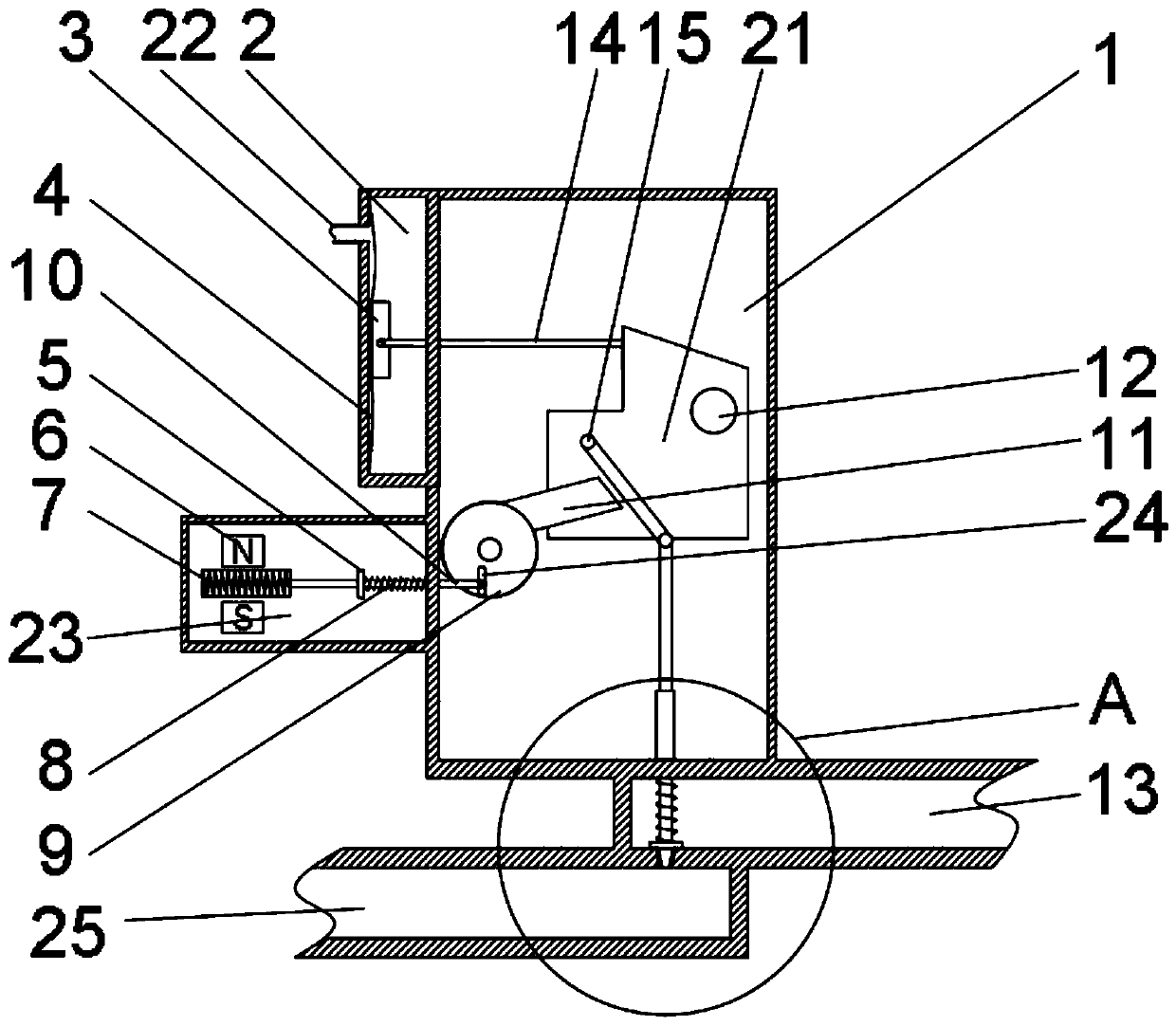
[0003] The existing safety valve usually only has one safety guarantee. The mechanical safety valve relies on the pressure of the working medium to overcome the mechanical load imposed on the disc by the loading mechanism to open and close the safety valve. Since the safety valve is directly in contact with the working medium, this leads to Scale and other impurities block or corrode the safety valve, leaving hidden dangers for safety. Electromagnetic safety valves usually have poor reliability, long maintenance time for solenoid valves, and high replacement costs

Method used


Image

  • Safe hydraulic valve for hydraulic electric control system
  • Safe hydraulic valve for hydraulic electric control system
  • Safe hydraulic valve for hydraulic electric control system

Examples


Embodiment Construction

[0028] The present invention will be further described in detail below in conjunction with the accompanying drawings and specific embodiments.

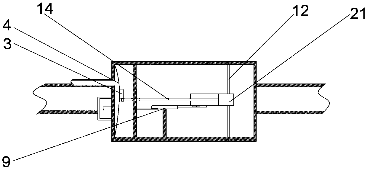
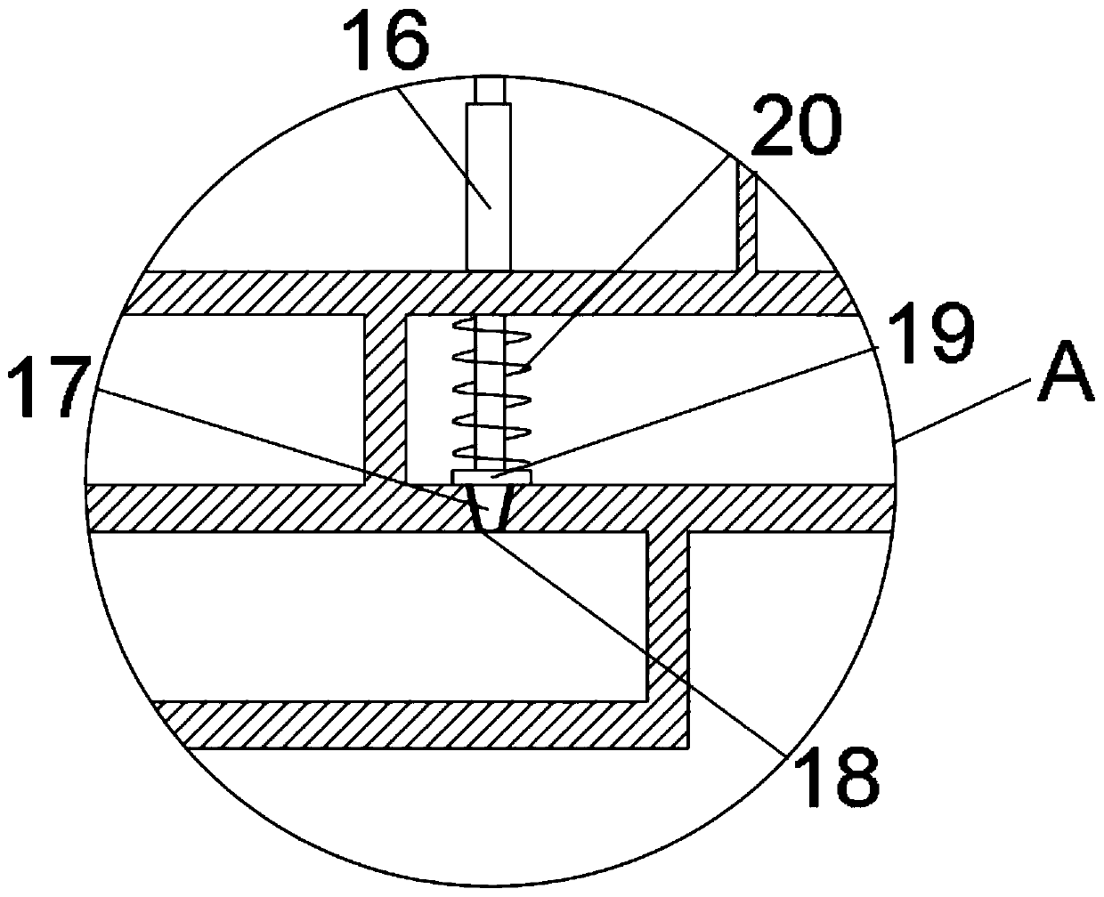
[0029] as attached figure 1 The shown safety hydraulic valve for a hydraulic electrical control system of the present invention includes a solenoid valve chamber 1, a side of the outer surface of the solenoid valve chamber 1 is fixedly connected with a pressure measuring chamber 2, and a piston 3 is installed inside the pressure measuring chamber 2. One side of the outer surface of 3 is fixedly connected with a membrane 4, and the end of the piston 3 away from the membrane 4 is fixedly connected with a piston rod 14, and the membrane 4 is fixedly connected with the bottom end of the pressure measuring chamber 2, and the piston rod 14 penetrates the inner wall of the pressure measuring chamber 1, The film 4 can make the airtightness of the pressure vessel better, and the film 4 is soft in texture and has high pressure response sensitiv...


PUM


Abstract

The invention relates to a safe hydraulic valve and belongs to the technical field of safety protection. The safe hydraulic valve for a hydraulic electric control system comprises an electromagnetic valve cavity. One side of the outer surface of the electromagnetic valve cavity is fixedly connected to a pressure measuring cavity, a piston is mounted in the pressure measuring cavity, the outer surface of one side of the piston is fixedly connected to a film, the end, far away from the film, of the piston is fixedly connected to a piston rod, the upper end of the pressure measuring cavity is fixedly connected to a pressure guiding pipe, an electromagnetic control cavity is fixedly connected below the pressure measuring cavity, two permanent magnets are mounted in the electromagnetic controlcavity, and a coil winding is slidably mounted between the two permanent magnets. The reliability of the safe valve can be improved. The safe hydraulic valve provided with two safety mechanisms: the electromagnetic control cavity and the pressure measuring cavity works by means of the mechanical pressure measuring cavity under a normal circumstance. When the film of the pressure measuring cavity is blocked or damaged, the electromagnetic valve cavity is put into work, so that the integral reliability of the safe valve is guaranteed and the maintenance cost of the safe valve is lowered.

Description

technical field [0001] The invention relates to a safety hydraulic valve, in particular to a safety hydraulic valve for a hydraulic electric control system. Background technique [0002] The safety valve is a special valve whose opening and closing parts are in a normally closed state under the action of external force. When the medium pressure in the equipment or pipeline rises above the specified value, it discharges the medium to the outside of the system to prevent the medium pressure in the pipeline or equipment from exceeding the specified value. . Safety valves are automatic valves, mainly used in boilers, pressure vessels and pipelines, to control the pressure not to exceed the specified value, and play an important role in protecting personal safety and equipment operation. [0003] The existing safety valve usually only has one safety guarantee. The mechanical safety valve relies on the pressure of the working medium to overcome the mechanical load imposed on the ...

Claims


Application Information

Patent Timeline
IPC IPC(8): F16K31/124F16K31/06F16K31/44F16K17/19
CPCF16K17/19F16K31/0644F16K31/124F16K31/44F16K31/0655F16K31/082F16K31/52
Inventor 王刚唐弇冬周皓
Owner PAGMAN TECH (TAICANG) CO LTD
Learn More