Quartz vibrating beam accelerometer sensitive assembly

An accelerometer and vibrating beam technology, which is applied in the field of sensitive components of quartz vibrating beam accelerometers, can solve the problems of thermal expansion coefficient mismatch, difficult processing of side electrodes, and high cost

Inactive Publication Date: 2020-04-10
BEIJING AUTOMATION CONTROL EQUIP INST
View PDF4 Cites 3 Cited by
  • Summary
  • Abstract
  • Description
  • Claims
  • Application Information

AI Technical Summary

Problems solved by technology

[0005] 1. The coefficient of thermal expansion does not match
The quartz vibrating beam accelerometer is mainly sensitive to external stress. When the thermal expansion coefficients of the quartz vibrating beam and the metal pendulum are inconsistent, and when the ambient temperature changes, the expansion and contraction ratios of the quartz vibrating beam and the metal pendulum are inconsistent, resulting in a Generate large internal stress, which greatly affects the measurement accuracy of the accelerometer;
[0006] 2. Large cross-coupling
It is manifested that the output changes greatly before and after vibration, and due to the large cross-coupling coefficient, the vibration rectification error is relatively large during the vibration process
[0007] 3. Difficult to process
The narrow gap unique to the double interdigitated quartz beam makes it difficult to process side electrodes
[0008] 4. High cost
The metal pendulum is machined, because of its high requirements for dimensional accuracy and consistency, resulting in high processing costs

Method used


Image

  • Quartz vibrating beam accelerometer sensitive assembly
  • Quartz vibrating beam accelerometer sensitive assembly

Examples


Embodiment Construction

[0020] Specific embodiments of the present invention will be described in detail below in conjunction with the accompanying drawings. In the following description, for purposes of explanation and not limitation, specific details are set forth in order to provide a thorough understanding of the invention. It will be apparent, however, to one skilled in the art that the present invention may be practiced in other embodiments that depart from these specific details.

[0021] It should be noted here that, in order to avoid obscuring the present invention due to unnecessary details, only the device structure and / or processing steps closely related to the solution according to the present invention are shown in the drawings, and the steps related to the present invention are omitted. Invent other details that don't really matter.

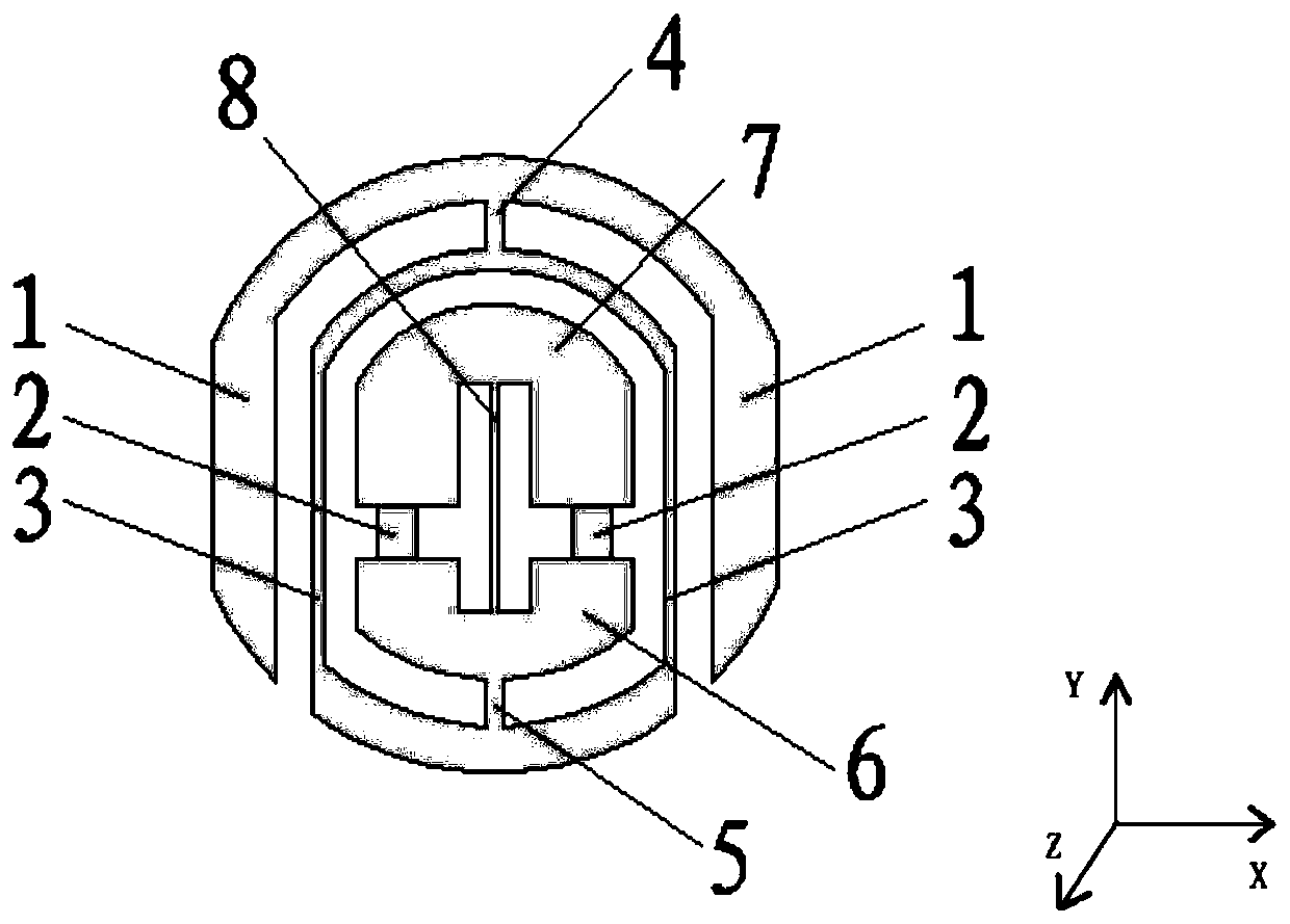
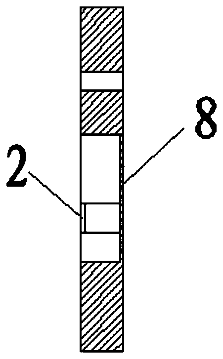
[0022] figure 1 A schematic structural diagram of a sensitive component of a quartz vibration beam accelerometer provided by an embodiment of the prese...


PUM


Abstract

The invention relates to the technical field of accelerometers, and discloses a quartz vibrating beam accelerometer sensitive assembly. The assembly comprises an outer frame, a flexible supporting piece, an isolation frame, an outer connecting piece, an inner connecting piece, a bracket, a detection mass block and a vibrating beam, the isolation frame is positioned in the outer frame; the outer side of one end of the isolation frame is connected with the inner side of the outer frame; the inner side of the other end of the isolation frame is connected with the bracket through inner connectors;one end of the vibration beam is connected with the detection mass block, the other end of the vibration beam is connected with the support, flexible supporting pieces are arranged between the upperend face of the support and the lower end face of the detection mass block and symmetrically distributed on the two sides of the vibration beam, the vibration beam and the flexible supporting pieces are not coplanar, and the flexible supporting pieces on the two sides are coplanar. Therefore, by additionally arranging the isolation frame and related components, a vibration beam energy dissipationchannel can be blocked, a double-interdigital structure is simplified into a single-interdigital structure, and a narrow gap is avoided. Moreover, the isolation frame can block the introduction of external thermal stress, thereby improving the temperature environment adaptability of the accelerometer.

Description

technical field [0001] The invention relates to the technical field of accelerometers, in particular to a sensitive component of a quartz vibrating beam accelerometer. Background technique [0002] The new generation of strategic weapons represented by cruise missiles, long-range bombers, submarines, intercontinental missiles, and hypersonic vehicles has an urgent need for small, high-precision accelerometers with high precision, high reliability, high stability, and low cost. Typical indicators are measurement range ±50g, bias stability 5μg, and scale factor stability 5ppm. At present, the pendulum gyro accelerometer (PIGA for short) is used, but its complex structure, large volume and weight, difficult maintenance and other characteristics are difficult to meet the development needs of future strategic weapons. The MEMS accelerometer based on the vibrating beam is the most important technical development direction of small high-precision accelerometers at present, which c...

Claims


Application Information

Patent Timeline
Patent Type & Authority Applications(China)
IPC IPC(8): G01P15/097G01P15/08
CPCG01P15/0802G01P15/097G01P2015/0808
Inventor 刘晓智张菁华孙刚丁凯苏翼马高印
Owner BEIJING AUTOMATION CONTROL EQUIP INST
Why Eureka
Try Eureka