Portable automatic discharge rod

An automatic discharge, portable technology, applied in the direction of measuring electricity, measuring electrical variables, instruments, etc., can solve the problems of no clear discharge time, long discharge time, and inability to judge, so as to save discharge time, speed up discharge speed, and improve work efficiency Effect

Active Publication Date: 2020-04-10
STATE GRID HEBEI ELECTRIC POWER CO LTD +2
View PDF15 Cites 5 Cited by
  • Summary
  • Abstract
  • Description
  • Claims
  • Application Information

AI Technical Summary

Problems solved by technology

However, the test guide requires that the large-capacity equipment be fully discharged many times before and after the test, but there is no clear discharge time, and it is impossible to judge whether it is completely discharged after the discharge. Therefore, in order to ensure safety before and after the test, the discharge time is generally longer. With the increase in the workload of high-voltage tests, the work efficiency of the ground discharge link needs to be effectively improved

Method used


Image

  • Portable automatic discharge rod
  • Portable automatic discharge rod
  • Portable automatic discharge rod

Examples


Embodiment 1

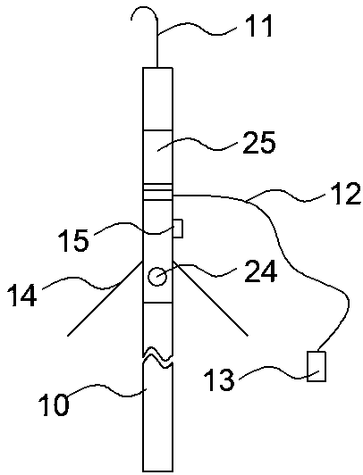
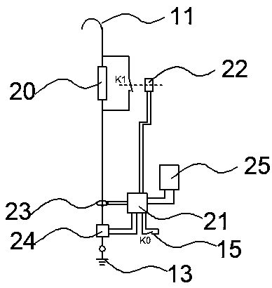
[0024] like figure 1 , 2 As shown in , 3 and 4, the present embodiment is a portable automatic discharge rod. Its body is an insulating rod 10 made of glass fiber material. A metal contact 11 and a discharge end connected to the metal contact 11 are provided. One end of the flexible wire 12 is fixedly or detachably connected to the discharge end, and the other end is connected to the grounding clamp 13 . After the metal contact 11 is connected to the high voltage resistor 20, it first passes through the current measuring device 23 and then connects the sound and light alarm 24 to connect with the grounding chuck 13. The current measuring device 23 is an active Hall current sensor, and the output terminal of the current measuring device 23 It is connected with the first input end of the control module 21 . The first output end of the control module 21 is connected to the control end of the short circuit switch 22 , the output end of the short circuit switch 22 is a normally o...

Embodiment 2

[0037] like Figure 4 , 5 As shown in , 6, this embodiment is a portable automatic discharge stick. The difference from Embodiment 1 is that this embodiment does not set a separate battery, so as to realize the safety of storage and use, and reduce the time cost of use at the same time. Therefore, the control module 21 is provided with a supercapacitor as a power supply; and is additionally provided with a discharge switching circuit formed by multiple sets of high-voltage resistors 20 and a short-circuit switch 22. When the discharge circuits R21 and R22 are connected in series, the total discharge resistance is the largest. When K1, K2 When both are in the conduction state, the discharge resistance is the smallest. When R21>R22, there can be four total discharge resistances from large to small R21+R22, R21, R22, and 0. The sound and light alarm 24 is the low power consumption OLED of the surrounding insulating rod 10 and the built-in buzzer of the insulating rod 10 .

[00...


PUM


Abstract

The invention provides a portable automatic discharge rod, and belongs to the technical field of high-voltage tests, and especially relates to a portable automatic discharge rod for releasing accumulated charges of a sample. The discharge rod comprises a metal contact arranged at one end of an insulating rod, and a grounding chuck connected with the metal contact through a flexible wire. A high-voltage resistor and a current measuring device are connected in series between the flexible wire and the metal contact. The output end of the current measuring device is connected with the input end ofa control module. The output end of the control module is connected with the control end of a short-circuit switch, and the output end of the short-circuit switch is connected with the high-voltage resistor in parallel. According to the invention, the discharge loop is arranged in a mode of parallel connection of the high resistance and the short-circuit line, the current measuring device and theautomatic switching device composed of the control module and the short-circuit switch are configured, and one normally closed contact of the short-circuit switch is arranged at the high resistance side, so that the short-circuit switch has discharge current testing and automatic switching functions.

Description

technical field [0001] The invention belongs to the technical field of high-voltage testing, and in particular relates to a portable automatic discharge rod for releasing the accumulated charge of a test object. Background technique [0002] In various on-site 10 kV, 35 kV, 110 kV high-voltage tests, especially after the DC withstand voltage test, it is necessary to fully discharge the charge accumulated on the test product to the ground to ensure personal safety. Whether the equipment or test objects are fully discharged before and after the test will seriously affect the safety of personal equipment. The size of the accumulated charge of the sample is proportional to the size of the capacitance of the sample and the level of the applied voltage and the length of time, so the discharge time required for different samples is also different. However, the test guide requires that the large-capacity equipment be fully discharged many times before and after the test, but there ...

Claims


Application Information

Patent Timeline
Patent Type & Authority Applications(China)
IPC IPC(8): G01R31/00
CPCG01R31/001
Inventor 赵京生赵伟候慧郭建戌张立辉齐红斌冯红刚孙政王家苗郭然王丹刘建洲麻石磊马连龙纪晗黎阳陆宇
Owner STATE GRID HEBEI ELECTRIC POWER CO LTD
Why Eureka
Try Eureka