
Nuclear fuel assembly and variable-rigidity pressing device

A nuclear fuel assembly and compression device technology, which is applied in the assembly of fuel elements, reactor fuel elements, nuclear engineering, etc., can solve the problems of insufficient compression force, large amount of irradiation relaxation, large stress of spring sheets, etc., to reduce bending risk, reducing creep relaxation, eliminating the effects of plastic deformation

Active Publication Date: 2020-04-10
GUANGDONG NUCLEAR POWER JOINT VENTURE +3
View PDF14 Cites 1 Cited by
  • Summary
  • Abstract
  • Description
  • Claims
  • Application Information

AI Technical Summary

Problems solved by technology

In addition, the pressing force provided by the leaf spring should not be too large, otherwise the fuel assembly will be greatly bent, which will affect the normal insertion of the control rod assembly, and will increase the hooking between adjacent fuel assembly grids during the hoisting process risk
[0004] In order to ensure safety, in the design of the existing leaf spring compression system, it has a large compression force margin, especially in the case of cold start, the actual compression force provided by the leaf spring is far greater than required The pressing force will cause the leaf spring to yield, so that there is a large stress inside the spring leaf
However, the stress received is large, and the amount of radiation relaxation is relatively large. After the spring is relaxed, the pressing force will become smaller, and there is a risk of insufficient pressing force in the middle and late stages of fuel assembly operation.
[0005] Existing compression devices are designed with constant stiffness. Excessive compression force margin under cold working conditions will lead to plastic deformation of the leaf spring, and in severe cases, it will cause bending of the fuel assembly, resulting in large creep relaxation due to irradiation stress

Method used


Image

  • Nuclear fuel assembly and variable-rigidity pressing device
  • Nuclear fuel assembly and variable-rigidity pressing device
  • Nuclear fuel assembly and variable-rigidity pressing device

Examples


Embodiment Construction

[0045] In order to have a clearer understanding of the technical features, purposes and effects of the present invention, the specific implementation manners of the present invention will now be described in detail with reference to the accompanying drawings.

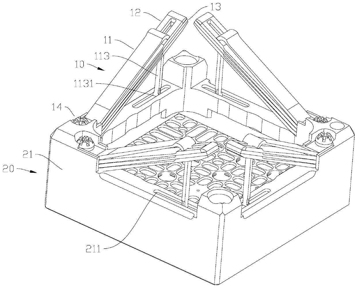
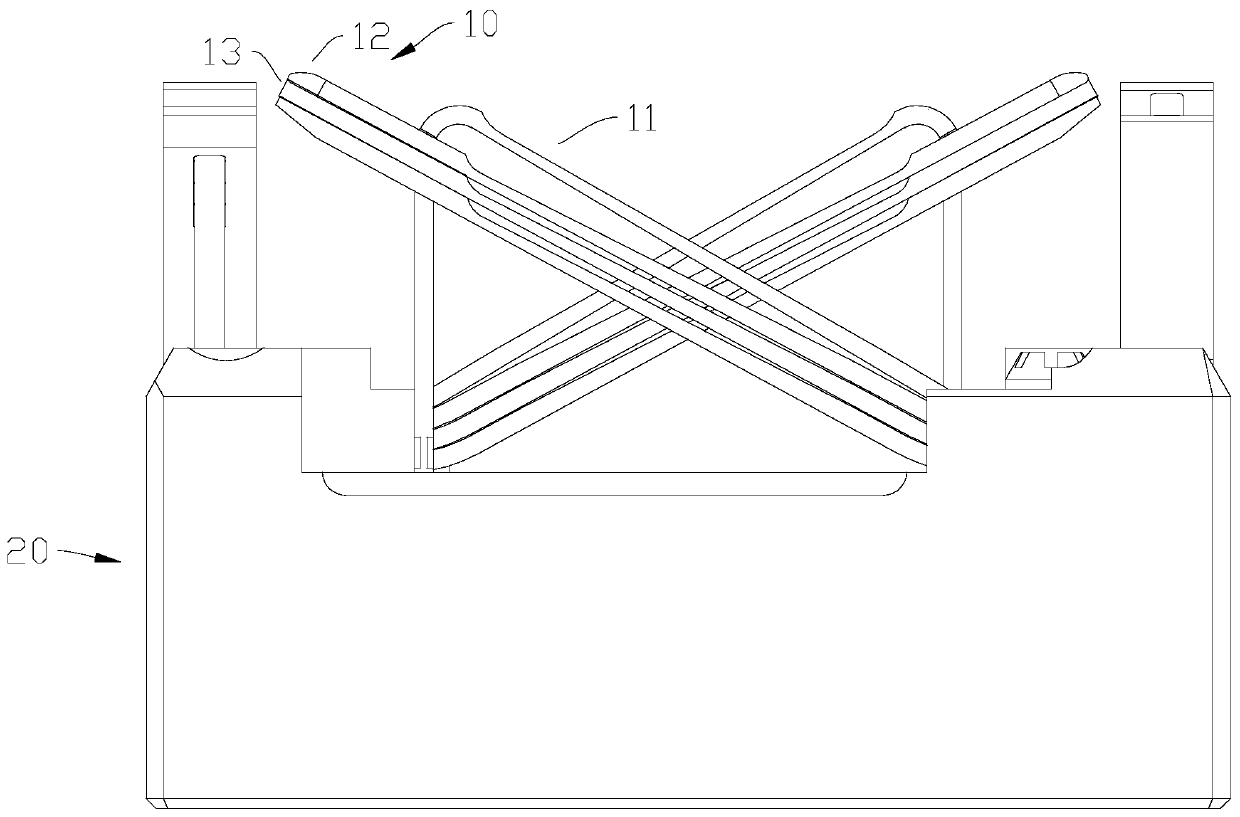
[0046] figure 1 and figure 2 Some preferred embodiments of the fuel assembly of the present invention are shown. The fuel assembly can be placed in a pressurized water reactor, which can avoid the risk of insufficient compaction force at the later stage of operation, and has the advantage of high safety performance. The pressing device in the fuel assembly of the present application adopts the design of variable stiffness according to the different requirements for the pressing force of the plate spring under the cold and hot states to achieve the purpose of obtaining an appropriate pressing force margin under different working conditions. It effectively alleviates the problems of excessive compression force margin u...


PUM


Abstract

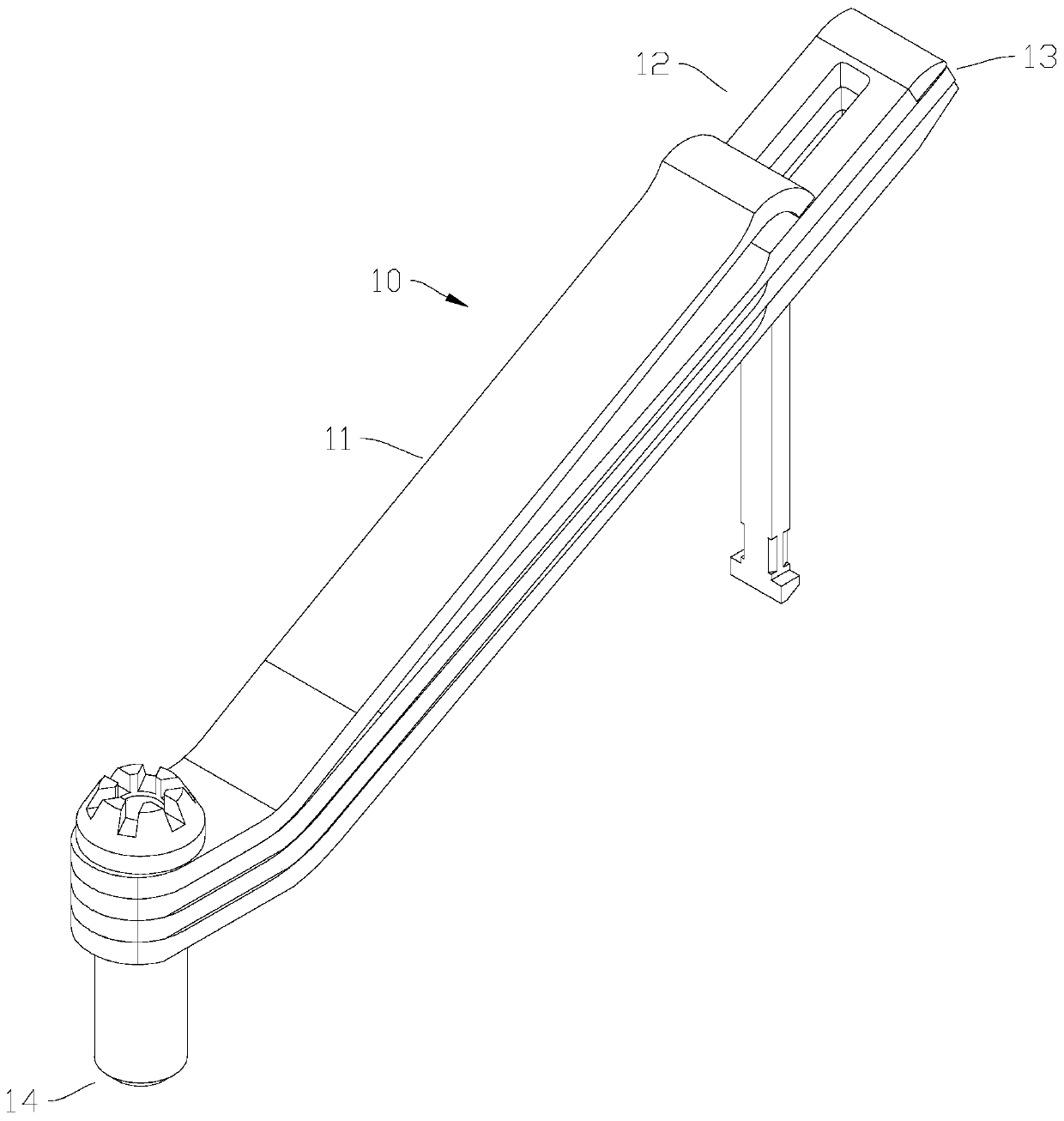
The invention relates to a nuclear fuel assembly and a variable-rigidity pressing device. The variable-rigidity pressing device comprises a plurality of pressing units. Each pressing unit comprises afirst plate spring and a second plate spring which are sequentially arranged in a stacked mode from top to bottom. The first plate spring comprises a first connecting arm, a first inclined arm obliquely extending at one end of the first connecting arm and a vertical arm arranged at the end, away from the first connecting arm, of the first inclined arm. The second plate spring comprises a second connecting arm and a second inclined arm obliquely extending at one end of the second connecting arm and stacked with the first inclined arm. A first window allowing the vertical arm to penetrate through is arranged in the section, away from the second connecting arm, of the second inclined arm, and the length of the second inclined arm is greater than that of the first inclined arm so that the highest point of the second inclined arm is higher than that of the first inclined arm. According to the variable-rigidity pressing device, plastic deformation of the plate spring can be reduced or eliminated, the bending risk of the fuel assembly can be reduced and irradiation stress creep relaxation can be reduced.

Description

technical field [0001] The invention relates to the technical field of nuclear reactors, in particular to a nuclear fuel assembly and a variable stiffness compression device. Background technique [0002] The existing PWR fuel assembly consists of fuel rods, upper and lower sockets, grids, guide pipes and the like. Among them, the pressing device and the upper nozzle form the upper nozzle part. The pressing device mainly realizes the compression of the fuel assembly, keeps the contact between the fuel assembly and the lower core plate, and compensates for the relationship between the fuel assembly and the upper and lower stacks after the fuel assembly is irradiated and grown. Difference in thermal expansion between core plates. [0003] The compression device, especially the compression leaf spring, is an important part in the PWR fuel assembly, and the fuel assembly compression system is composed of four leaf spring groups. The main function of the leaf spring set is to p...

Claims


Application Information

Patent Timeline
Patent Type & Authority Applications(China)
IPC IPC(8): G21C3/33
CPCG21C3/331Y02E30/30
Inventor 陈威庞铮铮金渊田玮刘贻潮李伟才傅先刚周跃民
Owner GUANGDONG NUCLEAR POWER JOINT VENTURE
Learn More