
Single 12-pulse rectifier transformer and equivalent multi-phase rectifier unit formed by same

A technology of pulse rectification and transformer, which is applied in the parts of transformer/inductor, transformer/inductor coil/winding/connection, transformer/inductor magnetic core, etc., which can solve the problem of uneven distribution of load current

Active Publication Date: 2020-04-10
朱祖乐
View PDF7 Cites 3 Cited by
  • Summary
  • Abstract
  • Description
  • Claims
  • Application Information

AI Technical Summary

Problems solved by technology

[0021] The purpose of the present invention is to propose a new solution to the problem of uneven load current distribution of the Y / Δ winding on the valve side of a single 12-pulse rectifier transformer

Method used


Image

  • Single 12-pulse rectifier transformer and equivalent multi-phase rectifier unit formed by same
  • Single 12-pulse rectifier transformer and equivalent multi-phase rectifier unit formed by same
  • Single 12-pulse rectifier transformer and equivalent multi-phase rectifier unit formed by same

Examples


Embodiment Construction

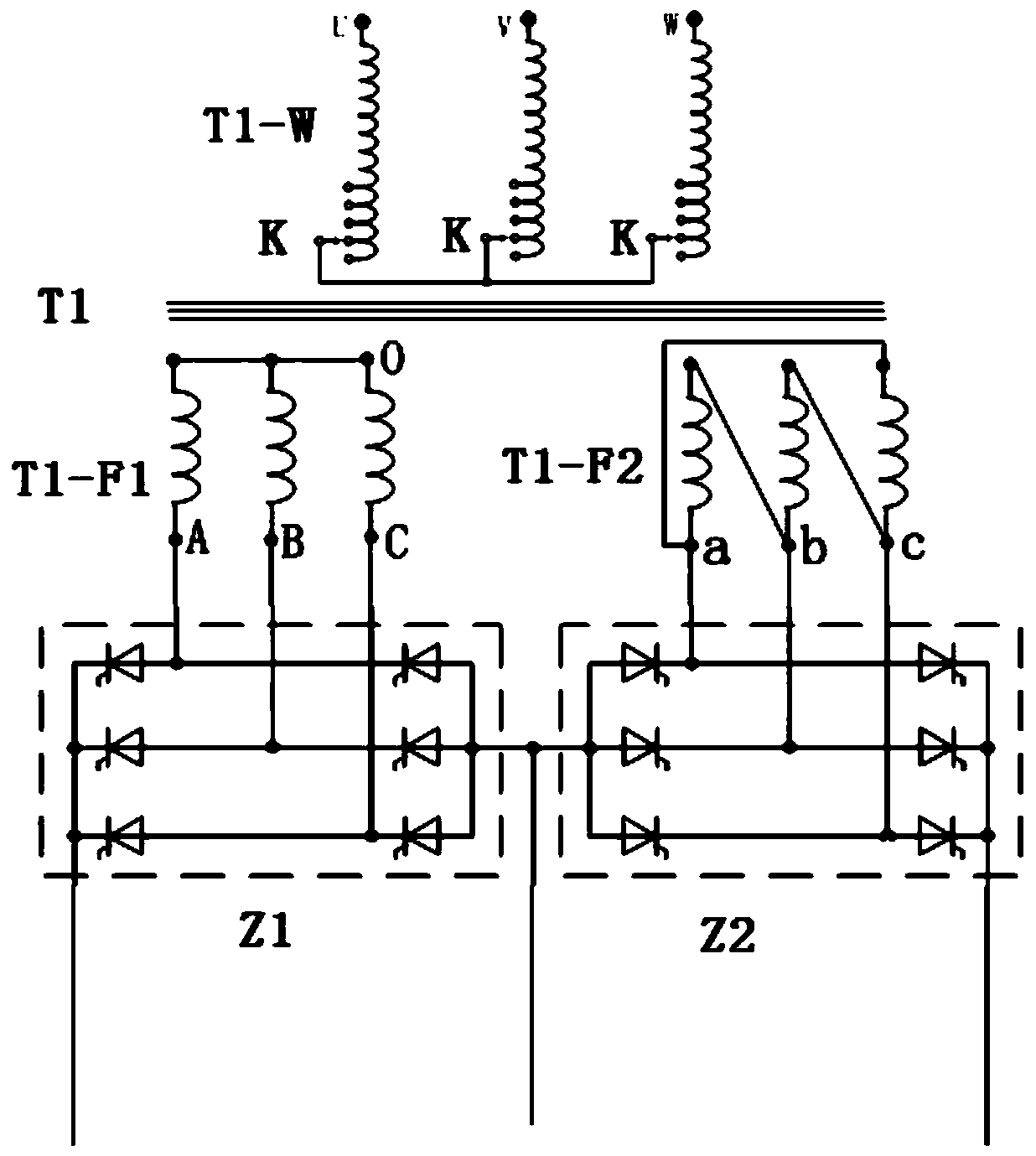
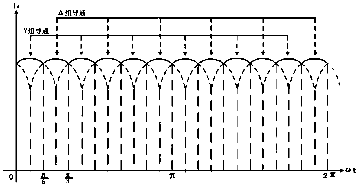
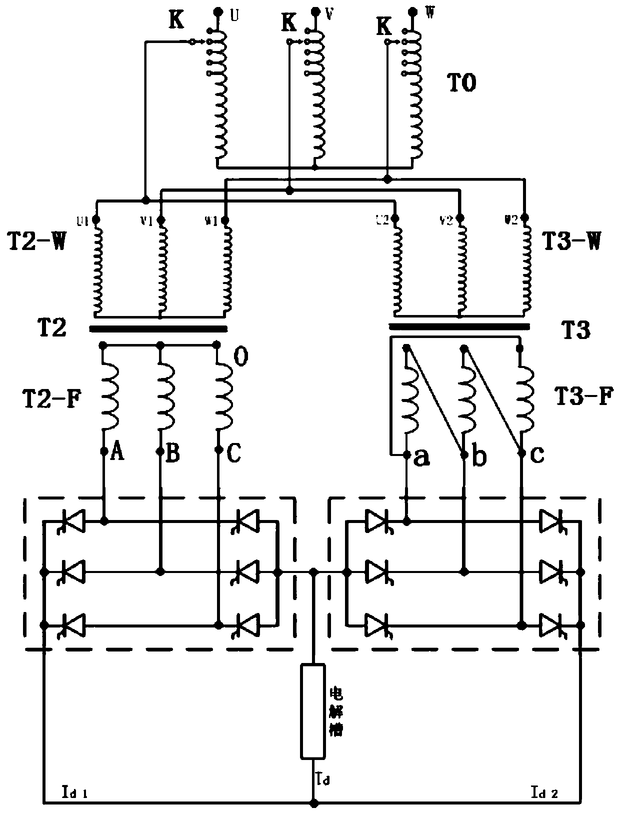
[0047] The single 12-pulse rectifier transformer of this embodiment is as Figure 6 As shown, it includes a rectification network side winding T1-W connected with an on-load switch K and two valve side windings. One of the two valve side windings is the Y winding T1-F1, and the other is the Δ winding T1-F2. Z1 and Z2 represent the rectification device powered by the Y winding and the rectifier device powered by the Δ winding respectively. In order to balance the voltage difference between the Y winding T1-F1 and the Δ winding T1-F2, the present invention designs and manufactures three through-type small single-phase auxiliary transformers T5 A , T5 B , T5c are respectively socketed on the main transformer T1 of the single 12-pulse rectifier transformer (consisting of the rectification network side winding T1-W and two valve side windings) on each phase line of the valve side Y winding T1-F1, and on the Y winding Each phase line of T1-F1 generates a complementary voltage with...


PUM


Abstract

The invention discloses a design scheme of a single 12-pulse rectifier transformer and an equivalent multi-phase rectifier unit formed by the same. The single 12-pulse rectifier transformer is additionally provided with three small single-phase auxiliary transformers. Iron cores of the small single-phase auxiliary transformers respectively sleeve circuits of each phase of the Y winding; primary windings on the iron cores are connected with the phase winding on the lines where the iron cores are located in parallel, a line penetrating through the iron cores serve as the secondary winding of theauxiliary transformer, and when the auxiliary transformer works, an in-phase compensation voltage is generated at the secondary stage, so that the phase voltage ratio of the Y winding to the [delta]winding is close to 1 / square root of 3. Compared with any scheme at present, in the scheme provided by the invention, the optimal voltage approaching value of the Y winding and the [delta] winding can be reached, the additional loss is relatively low, and the problems that the electrical parameters and economic benefits of the unit are influenced due to equalizing current and the like are solved.

Description

technical field [0001] The present invention relates to the field of 12-pulse rectifier units in large-scale electrochemical or electrometallurgical DC power supply systems, in particular to a single 12-pulse rectifier transformer, and to an equivalent multi-phase rectifier unit composed of the same . Background technique [0002] High-power rectifier units play an important role in the development of the national economy, and the performance and efficiency of the units directly affect energy utilization and economic benefits of enterprises. The impact of the harmonics generated by such a high-power rectifier unit on the local power grid cannot be ignored. Internationally, there are generally strict limits on the higher harmonics generated by the above-mentioned units. [0003] Large-scale enterprises often adopt equivalent polyphase system to reduce harmonic components. The principle of the equivalent polyphase system is to use an artificial method to make phase shifts b...

Claims


Application Information

Patent Timeline
Patent Type & Authority Applications(China)
IPC IPC(8): H01F27/40H01F27/42H01F27/245H01F27/25H01F27/26H01F27/28H01F27/30H01F27/33H01F27/34H02M7/06
CPCH01F27/245H01F27/25H01F27/263H01F27/266H01F27/28H01F27/306H01F27/33H01F27/346H01F27/40H01F27/42H02M7/068
Inventor 朱祖乐
Owner 朱祖乐
Learn More