Metal bipolar plate flow field runner structure of fuel cell

A metal bipolar plate, fuel cell technology, applied in the direction of fuel cells, fuel cell components, circuits, etc., can solve the problems of increased cost, increased performance requirements of booster equipment, and higher equipment selection requirements.

Active Publication Date: 2020-04-10
DALIAN INST OF CHEM PHYSICS CHINESE ACAD OF SCI
View PDF15 Cites 11 Cited by
  • Summary
  • Abstract
  • Description
  • Claims
  • Application Information

AI Technical Summary

Problems solved by technology

Although it strengthens the mixing and transfer of substances inside the fuel cell, due to the large number of continuous protrusions in the flow channel, it increases the difficulty of processing and manufacturing, and causes relatively greater fluid resistance.
Especially on the air side, the pressure drop caused by it will be more significant, which will lead to a significant increase in the performance requirements of the air compressor and other booster equipment, resulting in greater energy loss, higher requirements for equipment selection, and increased costs at the same time

Method used


Image

  • Metal bipolar plate flow field runner structure of fuel cell
  • Metal bipolar plate flow field runner structure of fuel cell
  • Metal bipolar plate flow field runner structure of fuel cell

Examples


Embodiment 1

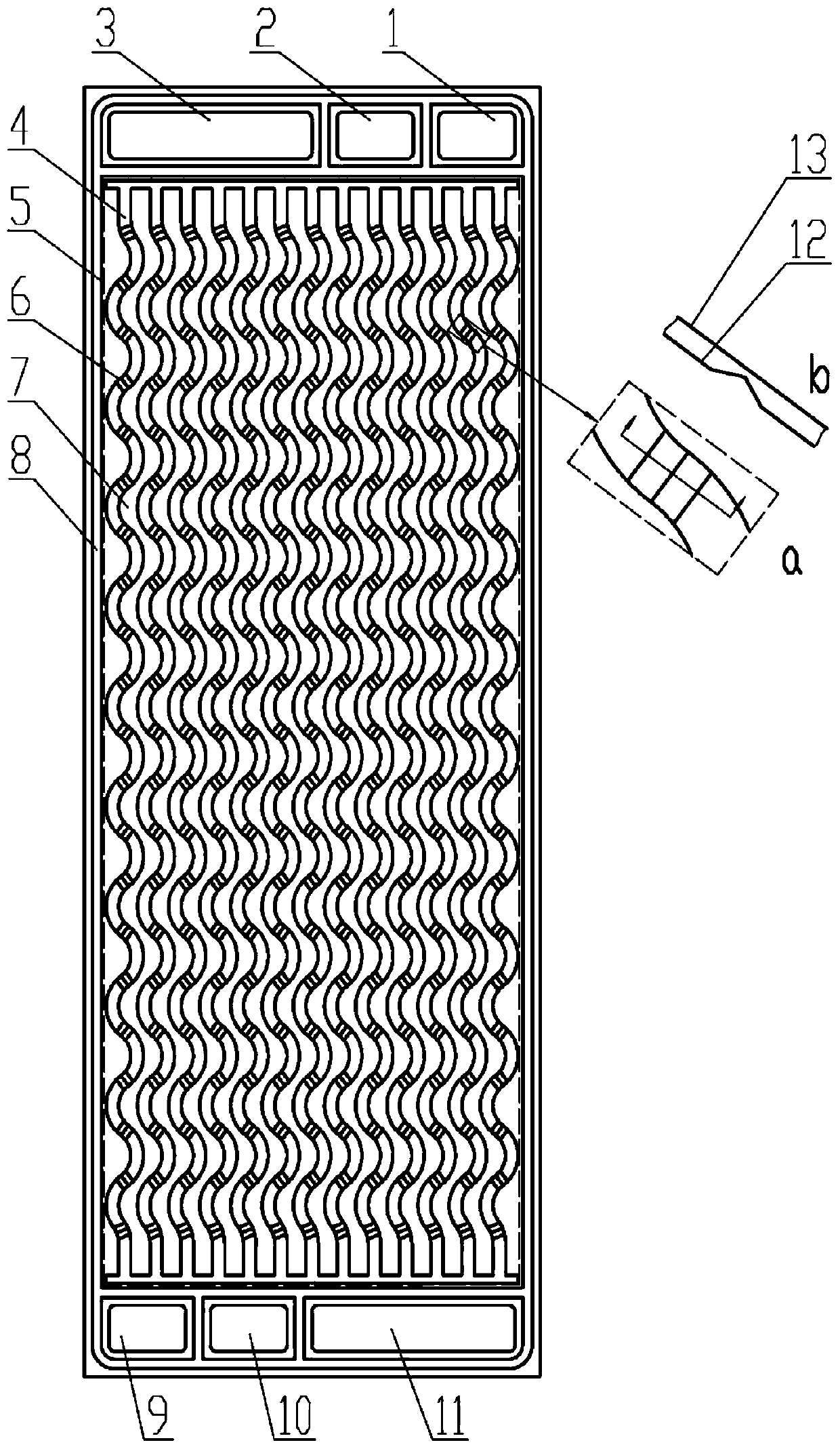
[0050] Embodiment 1: a kind of fuel cell metal bipolar plate ( figure 1 ), the bipolar plate includes a fuel gas inlet 9, a fuel gas outlet 1, an oxidant inlet 3, an oxidant outlet 11, a coolant inlet 2, a coolant outlet 10, an oxidant flow field and a fuel flow field, and the oxidant flow field and The fuel gas flow field is respectively located on the left and right sides of the bipolar plate, the oxidant inlet 3 and the oxidant outlet 11 are connected through the flow channel in the oxidant flow field, and the fuel gas inlet 9 and the fuel gas outlet 1 are connected through the flow channel in the fuel gas flow field. The flow channels are connected;

[0051] The oxidant inlet 3 and the oxidant outlet 11 are centrosymmetric with the center of the bipolar plate as the center point; the fuel gas inlet 9 and fuel gas outlet 1 are centrosymmetric with the center of the bipolar plate as the center point; the The coolant inlet 2 and the coolant outlet 10 are centrally symmetric...

Embodiment 2

[0056] Embodiment 2: Based on the bipolar plate described in Embodiment 1, only the structural size of the raised portion is adjusted, and the specific adjustment is as follows: the length of the raised portion is adjusted to 35 mm, and the distance between the raised portion in each flow channel is 40 mm. Layout, the rest of the size and structure remain unchanged.

Embodiment 3

[0057] Embodiment 3: Based on the bipolar plate described in Embodiment 1, only the structural size of the raised portion is adjusted, and the specific adjustments are as follows: the length of the raised portion is adjusted to 2 mm, the height of the raised portion is 0.4 mm, and the raised portion is at The inner spacing of each flow channel is 8 mm, and the arrangement is uniform, and the other dimensions and structures remain unchanged.


PUM

PropertyMeasurementUnit
lengthaaaaaaaaaa
heightaaaaaaaaaa

Abstract

The invention provides a metal bipolar plate of a fuel cell. The bipolar plate comprises a fuel gas inlet, a fuel gas outlet, an oxidant inlet, an oxidant outlet, an oxidant flow field and a fuel gasflow field, the oxidant flow field and the fuel gas flow field are respectively positioned on the left side and the right side of the bipolar plate, each of the oxidant flow field and the fuel gas flow field comprises M flow channels, and M is an integer greater than or equal to 1; and n discrete type protruding parts are arranged in each flow channel, the protruding parts are formed by protrudingbipolar plates located at the bottoms of the flow channels, N is an integer, and N is larger than or equal to 1. The oxidant inlet and the oxidant outlet are communicated through a flow channel in the oxidant flow field, and the fuel gas inlet and the fuel gas outlet are communicated through a flow channel in the fuel gas flow field. Through the plurality of convex parts arranged in the flow field flow channel, the mass transfer capability of the fuel cell is improved, and the performance of the fuel cell is further improved.

Description

technical field [0001] The invention relates to the technical field of fuel cells, in particular to a bipolar plate flow field channel structure for improving the performance of fuel cells and its application in fuel cells. Background technique [0002] Proton exchange membrane fuel cell (PEMFC) (hereinafter referred to as fuel cell) relies on electrochemical reactions to directly convert chemical energy stored in fuel gas (such as hydrogen) into electrical energy. The fuel cell power generation process has the characteristics of fast start-up at room temperature, high energy conversion efficiency, green and pollution-free exhaust gas, and safety. It can be widely used in fixed power stations, mobile power stations, aviation (sky) power generation, underwater equipment power generation, marine generators, and vehicle-mounted power generation. machine, field emergency power supply, portable power supply and other fields. In the world, with the increasing awareness of environ...

Claims


Application Information

Patent Timeline
Patent Type & Authority Applications(China)
IPC IPC(8): H01M8/026H01M8/0263
CPCH01M8/026H01M8/0263Y02E60/50
Inventor 艾军侯明郑利民邵志刚
Owner DALIAN INST OF CHEM PHYSICS CHINESE ACAD OF SCI
Why Eureka
Try Eureka