Phase-locked loop device for reducing frequency locking time and implementation method

A technology of frequency locking and phase-locked loop, which is applied in the field of phase-locked loop, can solve the problems of long locking time of high-performance phase-locked loop, inability to improve channel utilization, and lack of significant improvement in channel or time slot switching time, etc. , to achieve high-precision continuous optimization, short lock-up time, and reduce lock-up time

Active Publication Date: 2020-04-10
SHENZHNE DNS IND CO LTD
View PDF3 Cites 2 Cited by
  • Summary
  • Abstract
  • Description
  • Claims
  • Application Information

AI Technical Summary

Problems solved by technology

[0002] With the rapid development of wireless communication technology, the requirements for the utilization of radio frequency channel resources are getting higher and higher, and channel resources are becoming more and more tense. At the same time, high-performance radio frequency signals in professional applications also have high requirements for phase noise. The locking time of the high-performance phase-locked loop of the existing frequency hopping and TDMA radio frequency systems is relatively long, generally above 3ms, and the channel or time slot switching time has not been greatly improved, so the channel utilization rate cannot be improved. improve

Method used


Image

  • Phase-locked loop device for reducing frequency locking time and implementation method
  • Phase-locked loop device for reducing frequency locking time and implementation method
  • Phase-locked loop device for reducing frequency locking time and implementation method

Examples


Embodiment Construction

[0052] In order to make the above objects, features and advantages of the present invention more comprehensible, specific implementations of the present invention will be described in detail below in conjunction with the accompanying drawings. In the following description, numerous specific details are set forth in order to provide a thorough understanding of the present invention. However, the present invention can be implemented in many other ways different from those described here, and those skilled in the art can make similar improvements without departing from the connotation of the present invention, so the present invention is not limited by the specific implementations disclosed below.

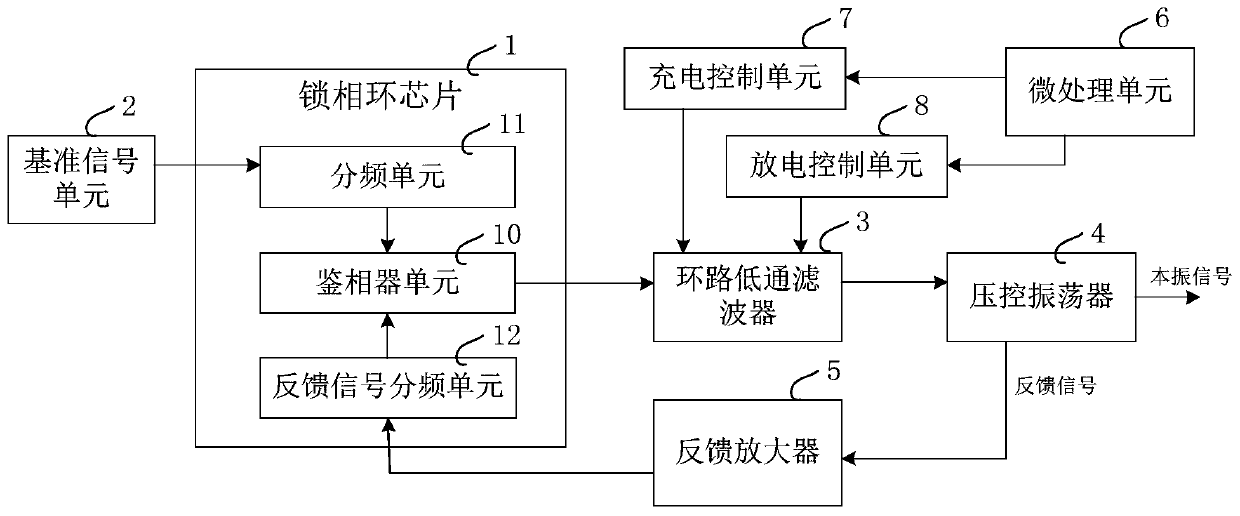
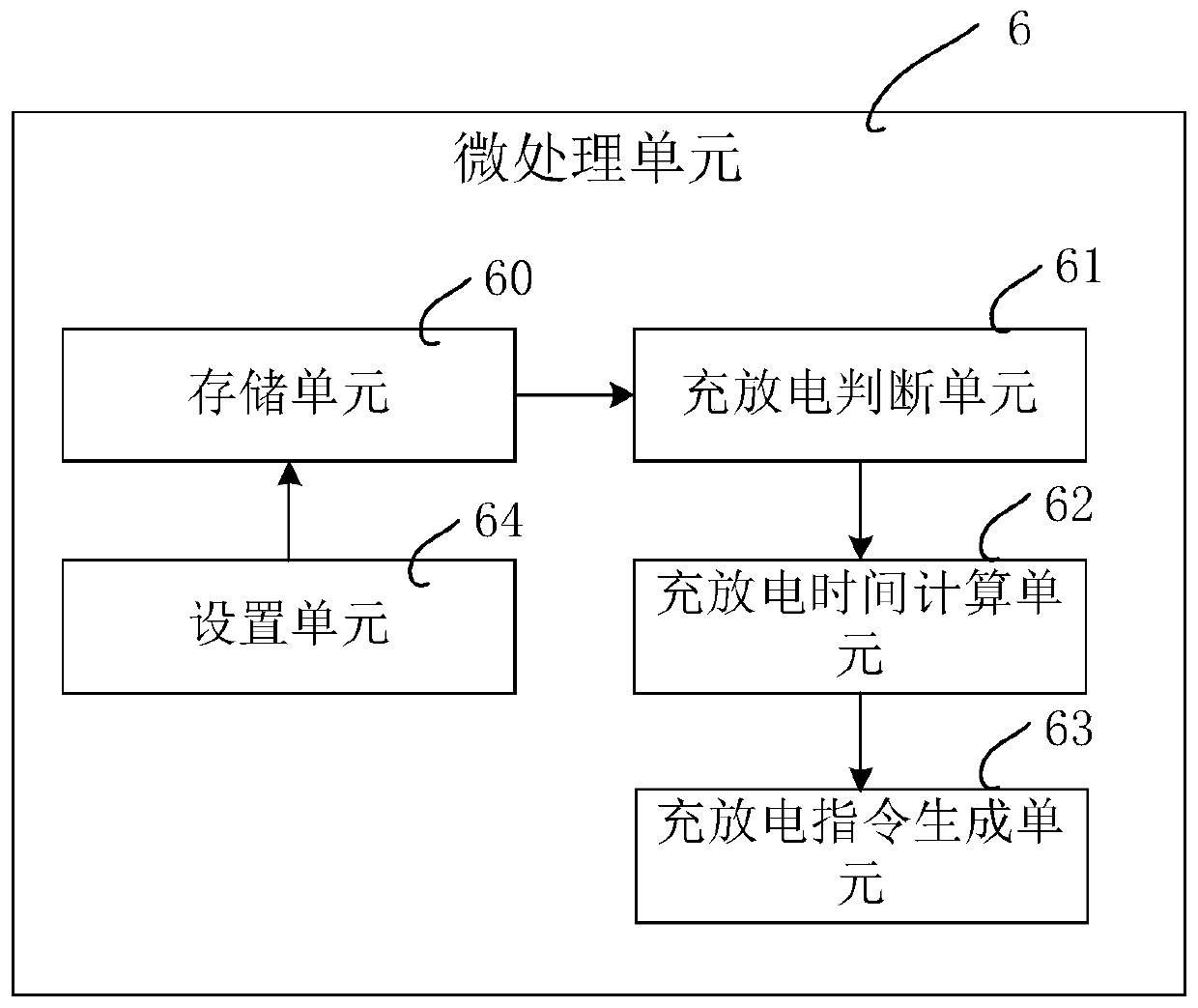
[0053] Please refer to figure 1 As shown, a schematic structural diagram of an embodiment of a phase-locked loop device for reducing frequency locking time provided by the present invention is shown; figure 2 As shown, in this embodiment, the phase-locked loop device for reducing th...


PUM


Abstract

The invention discloses a phase-locked loop device capable of reducing frequency locking time, which comprises a phase discriminator unit, a frequency division unit, a feedback signal frequency division unit, a loop low-pass filter, a voltage-controlled oscillator, a feedback amplifier, a micro-processing unit, and a charging control unit and a discharging control unit connected with the micro-processing unit, wherein the micro-processing unit is used for controlling the charging control unit or the discharging control unit to carry out charging and discharging operation on the loop low-pass filter during frequency switching so as to realize rapid locking. The invention further discloses a corresponding implementation method. By implementing the method disclosed in the invention, the voltage change time of the phase discrimination voltage during frequency hopping or time slot switching can be reduced, so that the frequency locking time is reduced, and meanwhile, the professional application requirement of high-phase noise is met.

Description

technical field [0001] The present invention relates to the technical field of phase-locked loops, in particular to a phase-locked loop device and an implementation method applied in TDMA (time-division multiplexing addressing) or fast frequency-hopping communication systems to reduce frequency locking time. Background technique [0002] With the rapid development of wireless communication technology, the requirements for the utilization of radio frequency channel resources are getting higher and higher, and channel resources are becoming more and more tight. At the same time, high-performance radio frequency signals in professional applications require high phase noise requirements, and The locking time of the high-performance phase-locked loop of the existing frequency hopping and TDMA radio frequency systems is relatively long, generally above 3ms, and the channel or time slot switching time has not been greatly improved, so the channel utilization rate cannot be improved....

Claims


Application Information

Patent Timeline
Patent Type & Authority Applications(China)
IPC IPC(8): H03L7/099
CPCH03L7/099Y02D30/70
Inventor 胡海平
Owner SHENZHNE DNS IND CO LTD
Why Eureka
Try Eureka