Use of a q&p steel for producing a shaped component for high-wear applications

A technology for uses and components, applied in the field of forming components, which can solve problems such as inability to obtain

Active Publication Date: 2020-04-10
THYSSENKRUPP STEEL EURO AG +1
View PDF8 Cites 2 Cited by
  • Summary
  • Abstract
  • Description
  • Claims
  • Application Information

AI Technical Summary

Problems solved by technology

No indication can be drawn in these texts that such steels are also used for wear purposes

Method used


Image

  • Use of a q&p steel for producing a shaped component for high-wear applications

Examples


Embodiment Construction

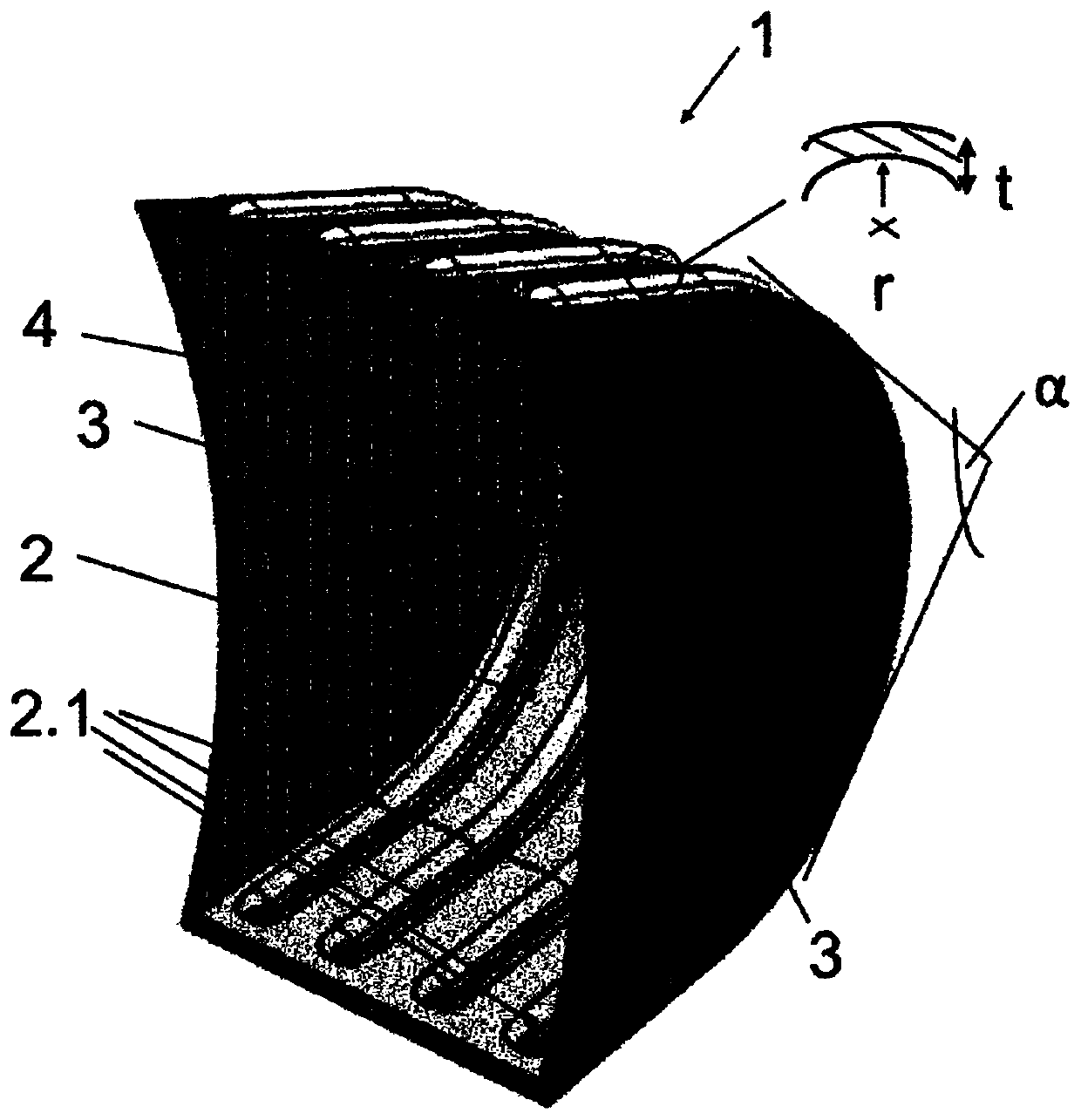
[0045] In the single figure, the excavator bucket (1) is shown in section. The excavator bucket (1) is, for example, a welded structure composed of three components (2, 3), consisting of a complexly shaped half shell (2) and two The side assembly (3) serves to create a cavity (4) open to one side for receiving waste material not shown. Along the partial circumference of the half shell (2), four embossments (2.1) running parallel to one another are formed, in particular for reinforcing the excavator bucket (1). Compared with the half shell without embossing, under the same performance, the material thickness (t) of the half shell (2) can be reduced by forming the embossing (2.1), so that the total weight of the excavator bucket (1) The weight is reduced and the loading capacity of the maximum allowable load of the excavator boom can be increased.

[0046] Components or half-shells (2) consist of Q&P steel which, in addition to Fe and production-induced unavoidable impurities,...


PUM

PropertyMeasurementUnit
hardnessaaaaaaaaaa
thicknessaaaaaaaaaa
thicknessaaaaaaaaaa

Abstract

The invention relates to a use of a Q&P steel for producing a shaped component (2) for high-wear applications, wherein the Q&P steel has a hardness of at least 230 HB, in particular at least 300 HB, preferably at least 370 HB, and a bending angle [alpha] of at least 60 DEG C, in particular at least 75 DEG C, preferably at least 85 DEG C, determined according to VDA238-100, and / or a bending ratio of r / t<2.5, in particular r / t<2.0, preferably r / t<1.5, wherein t corresponds to the material thickness of the steel and r corresponds to the (inner) bending radius of the steel.

Description

technical field [0001] The present invention relates to the use of Q&P steel for the production of formed components for wear applications. Background technique [0002] The wear steels known from the prior art are extremely hard for their application and have a correspondingly high strength and limited ductility. The purpose of the high hardness required in wear steels is a sufficiently high resistance to abrasive wear (abrasive Verschlei β). [0003] Conventional wear steels with high hardness usually have only limited formability and for example at a hardness of 400HB have a minimum bending ratio of eg about r / t=2.5, where in the bending of the steel r corresponds to the inner Radius, and t corresponds to the material thickness of the steel / component. With increasing hardness, the bending capacity of the steel deteriorates and bending ratios r / t<2.5 are no longer possible or only possible at high cost, whereby further processing of the steel, especially into complex ...

Claims


Application Information

Patent Timeline
Patent Type & Authority Applications(China)
IPC IPC(8): C22C38/02C22C38/04
CPCC22C38/02C22C38/04C21D8/02C22C38/06C22C38/38C22C38/58C21D1/18C21D2211/001C21D2211/002C21D2211/003C21D2211/005C21D2211/008C22C38/001C23C28/00C23G1/00C25D3/22
Inventor 尼娜·科尔贝帕特里克·库恩克莱门斯·拉图斯科理查德·格奥尔格·蒂森
Owner THYSSENKRUPP STEEL EURO AG
Why Eureka
Try Eureka