Internal combustion engine with gas-liquid separator for blowby gas

Active Publication Date: 2019-09-12
HONDA MOTOR CO LTD
View PDF4 Cites 1 Cited by
  • Summary
  • Abstract
  • Description
  • Claims
  • Application Information

AI Technical Summary

Benefits of technology

[0020]Since an end part of the PCV valve is positioned at the end part of the first gas-liquid separator in the first direction, the PCV valve can receive heat from the exhaust system. As a result, the temperature of the PCV valve is raised so that the freezing of moisture co

Problems solved by technology

When the ambient temperature drops below the freezing point, the moisture contained in the blowby gas may freeze in the gas-liquid separator, and the resulting ice may even clog the flow path of the blowby gas i

Method used


Image

  • Internal combustion engine with gas-liquid separator for blowby gas
  • Internal combustion engine with gas-liquid separator for blowby gas
  • Internal combustion engine with gas-liquid separator for blowby gas

Examples


Example

[0032]An automotive internal combustion engine according to an embodiment of the present invention is described in the following with reference to the appended drawings.

(Internal Combustion Engine Main Body)

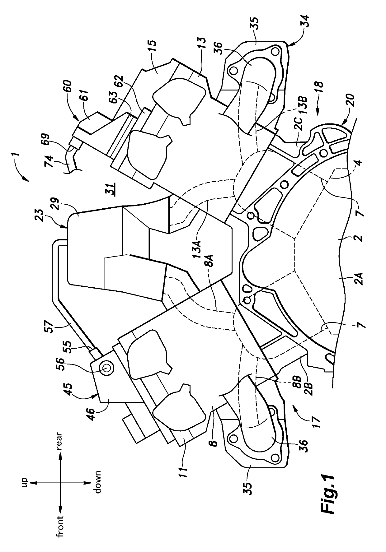
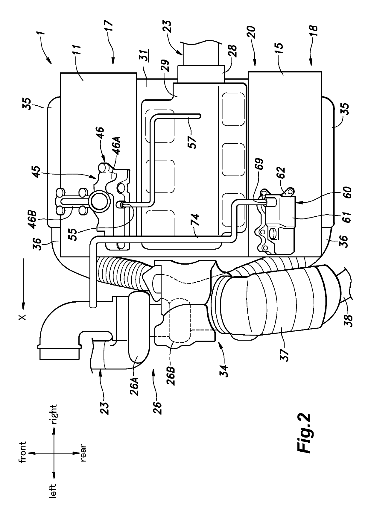
[0033]As shown in FIG. 1 and FIG. 2, the internal combustion engine 1 consists of a V-type engine, and is laterally mounted in an engine room of a vehicle so that the cylinder rows extend in the lateral direction (transverse direction). The internal combustion engine 1 includes a crankcase 2A provided in a lower part thereof, a front cylinder block 2B provided in an upper front side of the crankcase 2A, a rear cylinder block 2C provided in an upper rear side of the crankcase 2A. The crankcase 2A internally defines a crank chamber 4 that accommodates a crankshaft in a rotatable manner. The crankshaft extends along the cylinder row direction, or in the lateral direction. An oil pan is attached to a lower side of the crankcase 2A.

[0034]In each of the front cylinder block 2B and the ...


PUM


Abstract

An internal combustion engine (1) includes an internal combustion engine main body (20), a head cover (11, 15) attached to an upper end part of the internal combustion engine main body, and an exhaust system (34) connected to the internal combustion engine main body, and a gas-liquid separator (45, 60) for blowby gas provided in the head cover. A part of the exhaust system is positioned adjacent to the internal combustion engine main body in a first direction (X) along a cylinder row, and the gas-liquid separator is positioned in the head cover so as to be offset in the first direction.

Description

TECHNICAL FIELD[0001]The present invention relates to an internal combustion engine provided with a gas-liquid separator for blowby gas.BACKGROUND OF THE INVENTION[0002]It is known to provide a gas-liquid separator in a head cover of an internal combustion engine for separating oil contained in the blowby gas. When the ambient temperature drops below the freezing point, the moisture contained in the blowby gas may freeze in the gas-liquid separator, and the resulting ice may even clog the flow path of the blowby gas in the gas-liquid separator. To overcome this problem, it has been proposed to position the gas-liquid separator inside the head cover in such a manner that a gap is created between the gas-liquid separator and the head cover to minimize the influences of the ambient air on the gas-liquid separator. See JP2009-13941A, for example.[0003]However, according to this prior art, owing to the need to create a gap between the wall of the head cover and the gas-liquid separator, ...

Claims


Application Information

Patent Timeline
IPC IPC(8): F01M13/04F02F7/00
CPCF01M2013/0461F02F7/006F01M2013/0477F01M13/0416F01M13/0011F01M13/04F01M2013/0027F02B75/228F02M25/06F02M35/10222
Inventor TADA, KAZUSHI
Owner HONDA MOTOR CO LTD
Why Eureka
Try Eureka