High-precision polishing equipment for automobile parts

A high-precision technology for auto parts, applied in grinding/polishing equipment, metal processing equipment, parts of grinding machine tools, etc., can solve the problem of inability to polish auto parts, and achieve better polishing effect

Inactive Publication Date: 2020-04-14
王菊
View PDF6 Cites 3 Cited by
  • Summary
  • Abstract
  • Description
  • Claims
  • Application Information

AI Technical Summary

Problems solved by technology

A kind of polishing equipment for auto parts in the above-mentioned patents has certain shortcomings: during use, it cannot polish auto parts with a certain radian, and there are certain limitations in use. Therefore, it is urgent to design a high-precision auto parts Polishing equipment to solve the above problems

Method used


Image

  • High-precision polishing equipment for automobile parts
  • High-precision polishing equipment for automobile parts
  • High-precision polishing equipment for automobile parts

Examples


Embodiment 1

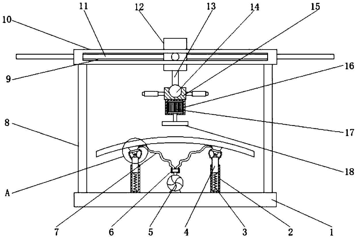
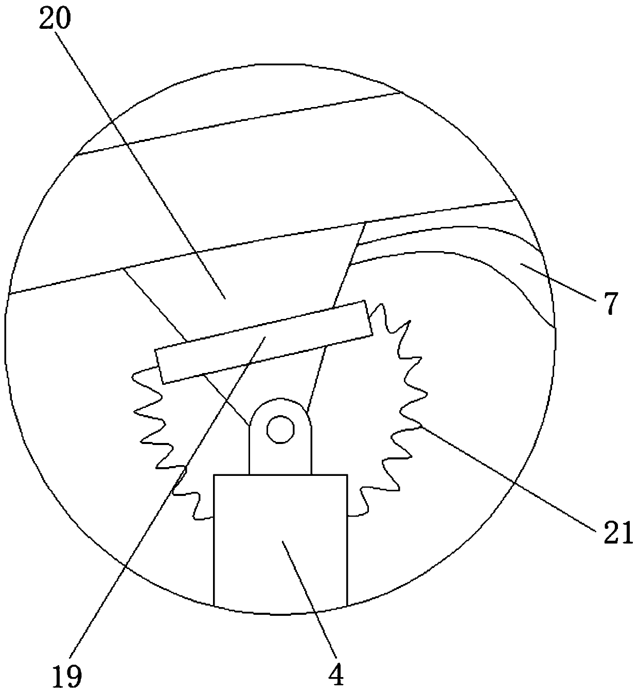
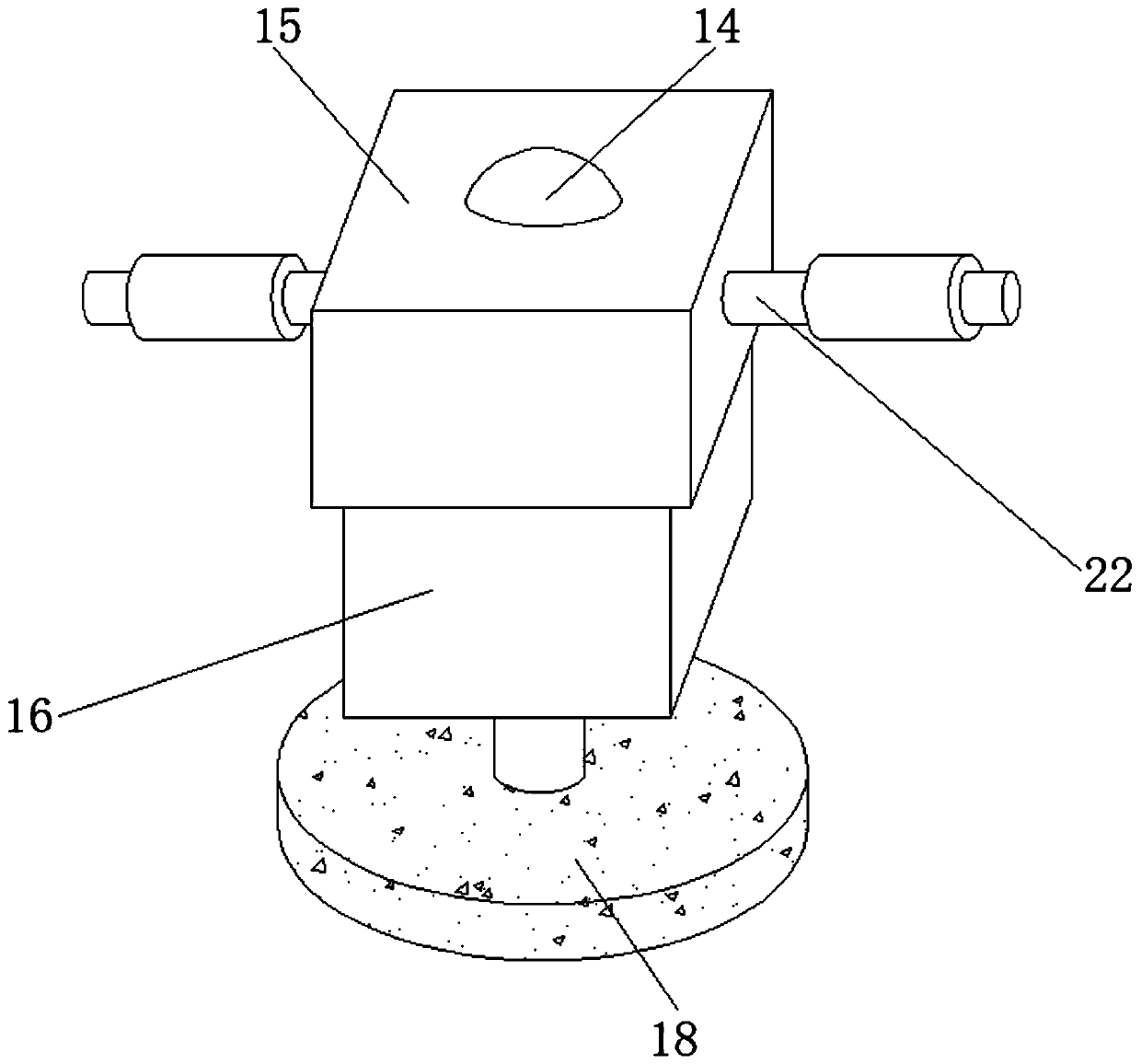
[0032] refer to Figure 1-4 , a kind of high-precision polishing equipment for automobile parts, comprising a bottom plate 1, four corners of the top outer wall of the bottom plate 1 are welded with fixed rods 8, and the top outer wall of the fixed rod 8 is welded with a fixed frame 10, and the outer walls around the fixed frame 10 are Have chute 9, and the inwall of chute 9 is slidably connected with slide bar 11, and the outer wall of one end of slide bar 11 is welded with movable case 12, and the top inner wall of movable case 12 is welded with the 3rd spring 23, the third spring 23 The bottom outer wall is welded with lifting plate 24, and the bottom outer wall of lifting plate 24 is welded with connecting rod 13, and the bottom outer wall of connecting rod 13 is welded with universal ball 14, and the outer wall of universal ball 14 is rotatably connected with movable seat 15, movable seat The bottom outer wall of 15 is welded with motor cover 16, and the inwall of motor c...

Embodiment 2

[0036] refer to Figure 5-7, a kind of high-precision polishing equipment for automobile parts. Compared with Embodiment 1, this embodiment also includes circular grooves 25 on the bottom outer wall of the polishing disc 18, and circular grooves 25 arranged on the inner wall of the circular groove 25. Groove 26, polishing disk 18 top outer walls are all provided with installation groove near the position of both sides, and the inwall of installation groove is provided with air guide pipe 27, and one end outer wall of air guide pipe 27 is connected with circular groove 25, and the air guide pipe 27 An air collecting pipe 28 is welded on the outer wall of the other end.

[0037] Working principle: when in use, when the polishing disc 18 rotates and polishes, the polishing debris generated by polishing will enter the chip removal groove 26, and the wind will enter the air guide pipe 27 through the air collecting pipe 28, and then blow through the air guide pipe 27. Enter the cir...


PUM


Abstract

The invention discloses high-precision polishing equipment for automobile parts. The equipment comprises a bottom plate; fixing rods are welded to the four corners of the outer wall of the top of thebottom plate correspondingly; a fixed frame is welded to the outer walls of the tops of the fixing rods; slide grooves are formed in the outer walls of the periphery of the fixed frame; the inner walls of the slide grooves are slidably connected with a sliding rod; a movable box is welded to the outer wall of one end of the sliding rod; a third spring is welded to the inner wall of the top of themovable box; a lifting plate is welded to the outer wall of the bottom of the third spring; a connecting rod is welded to the outer wall of the bottom of the lifting plate; a universal ball is weldedto the outer wall of the bottom of the connecting rod; a movable base is rotatably connected to the outer wall of the universal ball; a motor cover is welded to the outer wall of the bottom of the movable base; and a motor is connected to the inner wall of the motor cover through bolts. With the equipment of the invention adopted, automobile parts with different radians can be polished, and the automobile parts can be firmly adsorbed to suction cups. The equipment has the advantages of higher flexibility in use, higher stability in polishing and better polishing effect.

Description

technical field [0001] The invention relates to the technical field of auto parts processing, in particular to a high-precision polishing equipment for auto parts. Background technique [0002] Auto parts processing is the units that constitute the whole of auto parts processing and the products that serve the processing of auto parts. With the increasingly fierce competition in the auto parts processing market, the popularization of the concept of environmental protection, and the continuous upgrading and application of technology, in the production of automobiles In the production process, the processing equipment of auto parts is generally used, and the polishing machine is widely used in the processing of auto parts. [0003] After searching, the Chinese patent publication number is CN207387353U, which discloses a polishing equipment for auto parts, including a workbench, the inside of the workbench is provided with a moving plate, and the bottom of the moving plate is f...

Claims


Application Information

Patent Timeline
Patent Type & Authority Applications(China)
IPC IPC(8): B24B29/02B24B41/02B24B41/06B24B55/06B24B41/04
CPCB24B29/02B24B41/02B24B41/04B24B41/06B24B55/06
Inventor 王菊
Owner 王菊
Why Eureka
Try Eureka