Industrial robot hand-eye calibration method based on calibration ball

A technology of industrial machines and calibration methods, applied in the field of 3D vision, can solve the problems of low precision, time-consuming and laborious, cumbersome and other problems, and achieve the effect of high precision, ensuring reliability and convenient operation.

Inactive Publication Date: 2020-04-14
JIANGSU JICUI MICRO NANO AUTOMATION SYST & EQUIP TECH RES INST CO LTD
View PDF12 Cites 8 Cited by
  • Summary
  • Abstract
  • Description
  • Claims
  • Application Information

AI Technical Summary

Problems solved by technology

[0003] In the process of parts inspection, we usually need to calibrate the robotic arm and 3D camera of the robot first. The traditional hand-eye calibration method is cumbersome, requires multiple sampling, and manual operation, which is time-consuming and labor-intensive, and the accuracy is not high.

Method used


Image

  • Industrial robot hand-eye calibration method based on calibration ball
  • Industrial robot hand-eye calibration method based on calibration ball
  • Industrial robot hand-eye calibration method based on calibration ball

Examples


Embodiment Construction

[0024] The present invention will be further described below in conjunction with the accompanying drawings and specific embodiments, so that those skilled in the art can better understand the present invention and implement it, but the examples given are not intended to limit the present invention.

[0025] refer to Figure 1-Figure 2 As shown, the present invention discloses a hand-eye calibration method for an industrial robot based on a calibration ball, comprising the following steps:

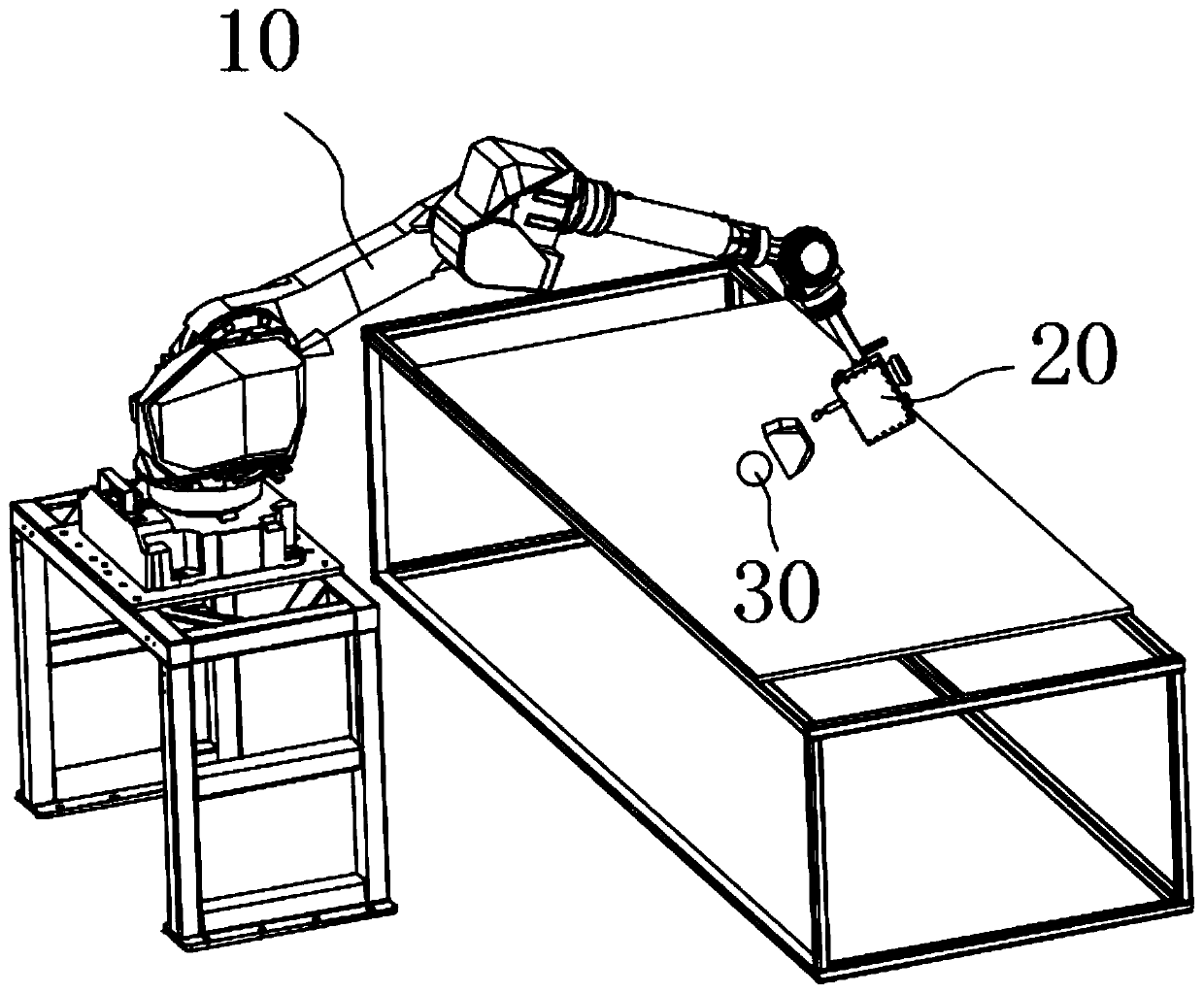
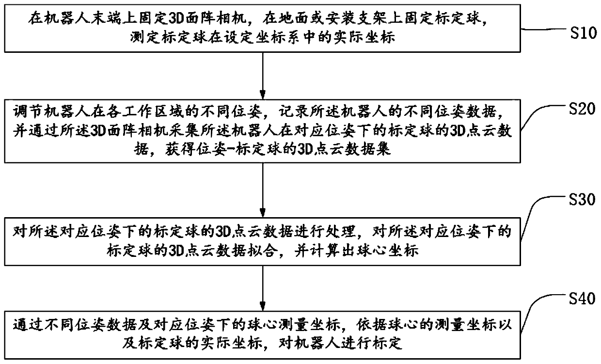
[0026] Step 1: Fix the 3D area camera 20 on the end of the robot 10, fix the calibration ball 30 on the ground or on the mounting bracket, and measure the actual coordinates of the calibration ball in the set coordinate system. The calibration ball is a ceramic positioning ball. The ceramic positioning ball is fixed on the ground through a mounting bracket.

[0027] Step 2, adjusting the different poses of the robot in each working area, recording the different pose data of the robot, and...


PUM


Abstract

The invention discloses an industrial robot hand-eye calibration method based on a calibration ball, and the method comprises the following steps: fixing a 3D area-array camera at the tail end of a robot, fixing the calibration ball on the ground, and measuring the actual coordinates of the calibration ball; adjusting different poses of the robot in each working area, recording different pose dataof the robot, and acquiring 3D point cloud data of the calibration ball of the robot under the corresponding pose through the 3D area-array camera to obtain a pose-calibration ball 3D point cloud data set; processing the 3D point cloud data of the calibration ball under the corresponding pose, fitting the 3D point cloud data of the calibration ball under the corresponding pose, and calculating aball center coordinate; and calibrating the robot through the different pose data and sphere center measurement coordinates under the corresponding pose as well as the actual coordinates of the calibration ball. The method facilitates calibration of the robot, is simple and easy to implement, and is quick and accurate.

Description

technical field [0001] The invention relates to the technical field of 3D vision, in particular to a hand-eye calibration method for an industrial robot based on a calibration ball. Background technique [0002] The robot's motion coordinate system and the camera's coordinate system are combined through "hand-eye calibration". Here, the end effector of the robot can be regarded as a human hand, and the visual sensor can be regarded as a human eye. Robot hand-eye systems are generally divided into two types, eye-in-hand and eye-to-hand. The former fixes the visual sensor on the end effector of the robot, which can follow the end of the robot. Motion, which fixes the vision sensor in the environment and does not move with the end of the robot. The former tend to have higher dexterity and allow for greater precision in the robot's movements. [0003] In the process of parts inspection, we usually need to calibrate the robotic arm and 3D camera of the robot first. The traditio...

Claims


Application Information

Patent Timeline
Patent Type & Authority Applications(China)
IPC IPC(8): B25J9/16
CPCB25J9/1653B25J9/1692
Inventor 葛继李剑锋宫正汝长海孙钰
Owner JIANGSU JICUI MICRO NANO AUTOMATION SYST & EQUIP TECH RES INST CO LTD
Why Eureka
Try Eureka