Slurry discharging device for ceramic production

A technology of ceramics and suits, applied in the field of ceramic processing, can solve problems such as low production efficiency, adhesion between the embryo body and the template, and difficulty in starting the mold, so as to accelerate the loss of water and avoid adhesion damage

Pending Publication Date: 2020-04-14
醴陵市和泰陶瓷制造有限公司
View PDF0 Cites 3 Cited by
  • Summary
  • Abstract
  • Description
  • Claims
  • Application Information

AI Technical Summary

Problems solved by technology

[0003] The purpose of the present invention is to solve the technical problem that the existing ceramic slurry discharge device often takes a long time to complete the molding of the embryo body, the production efficiency is low, and the phenomenon that the embryo body and the template are easy to stick together is difficult to remove the mold. It provides A slurry discharge device for ceramic production

Method used


Image

  • Slurry discharging device for ceramic production
  • Slurry discharging device for ceramic production
  • Slurry discharging device for ceramic production

Examples


Embodiment Construction

[0024] In order to make the purpose, technical solutions and advantages of the embodiments of the present invention clearer, the technical solutions in the embodiments of the present invention will be clearly and completely described below in conjunction with the drawings in the embodiments of the present invention. Obviously, the described embodiments It is a part of embodiments of the present invention, but not all embodiments.

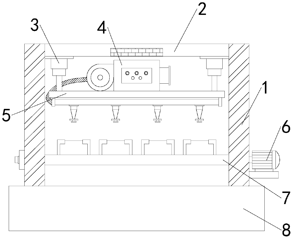
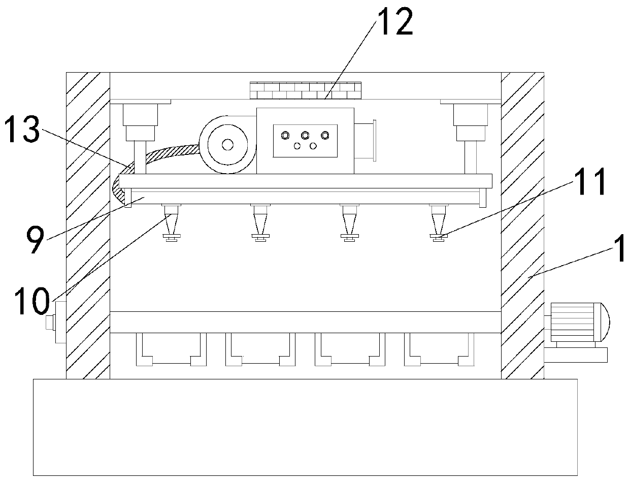
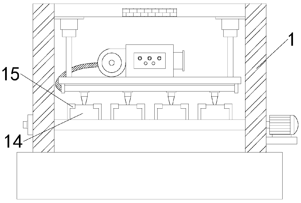
[0025] see Figure 1-4 , in an embodiment of the present invention, a slurry discharge device for ceramic production, including an outer support 1, a slurry discharge assembly and a drying assembly, the drying assembly and the slurry discharge assembly are installed on the inner side of the outer support 1 from top to bottom;

[0026] The slurry discharge assembly includes a servo motor 6, a placement plate 7, a slurry discharge tank 8, a plaster mold 14, a clamping piece 15, a central shaft 16 and a placement groove 17, and the placement plate 7 is...


PUM


Abstract

The invention provides a slurry discharging device for ceramic production, which relates to the technical field of ceramic processing. The device comprises an outer support, a slurry discharging assembly and a drying assembly, wherein the drying assembly and the slurry discharging assembly are installed on the inner side of the outer support from top to bottom; the slurry discharging assembly comprises a servo motor, a placing plate, a slurry discharging groove, a gypsum mold, a clamping piece, a middle shaft and a placing groove; the placing plate is movably installed on the lower middle portion of the inner side of the outer support through a middle shaft; the servo motor is fixedly installed on the outer wall of one side of the outer support and corresponds to the placing plate; the slurry discharging groove is fixedly formed in the bottom of the outer support; the placing groove is formed in the upper surface of the placing plate; and the clamping piece is connected to the periphery of the placing groove in a hinged mode. According to the device, a hot-air blower and an air nozzle are arranged, the hot-air blower conducts hot drying on the blank in the mold through the air nozzle, moisture of the blank is dissipated in an accelerated mode, the dry blank is obtained, and therefore the dry blank is not prone to adhering to a mold plate and suitable for production and use of the slurry discharging device for ceramic production.

Description

technical field [0001] The invention relates to the technical field of ceramic processing, in particular to a slurry discharge device for ceramic production. Background technique [0002] Grouting molding is a molding method of pouring mud into a plaster mold to make it into a product. It is suitable for batch molding of complex shapes or large products. The grouting molding method is relatively simple, that is, the mud made from the blank is injected into the plaster model. Because gypsum is water-absorbent, the water in the mud near the inner wall of the model is sucked by the porous gypsum to form a mud layer with the same shape as the inner wall of the model on the inner wall of the plaster mold. This mud layer increases with time. thickened. After a period of time, the excess mud is poured out, and the mud layer close to the inner wall of the plaster model remains in the model. After a period of time, the mud layer naturally shrinks and separates from the model, and th...

Claims


Application Information

Patent Timeline
Patent Type & Authority Applications(China)
IPC IPC(8): B28B1/26B28B11/24B28B17/00
CPCB28B1/26B28B1/264B28B11/243B28B17/00B28B17/0081
Inventor 帅建帅志帅卓
Owner 醴陵市和泰陶瓷制造有限公司
Why Eureka
Try Eureka