Winding ring device, winding device and tire bead winding system

A technology for winding rings and beads is applied in the field of auxiliary equipment for tire production, which can solve the problems of winding quality, inconsistent tension, and low winding quality, and achieve the effects of high winding stability, no material waste, and improved winding quality.

Active Publication Date: 2020-04-14
LINK-ASIA SMART TECH (SUZHOU) CO LTD
View PDF6 Cites 2 Cited by
  • Summary
  • Abstract
  • Description
  • Claims
  • Application Information

AI Technical Summary

Problems solved by technology

And the strip is stacked and stored on the roller part for multiple turns. Since the strip has a certain thickness, when the strip is released from the roller part, the diameter of the strip material roll stored on the roller part will gradually decrease. However, due to the The damping of the roller part is fixed and will not change with the diameter of the strip from the beginning to the end of the winding, so that the tension of the strip released by the roller part changes with the change of the roll diameter, causing the winding The tension on the bare bead is inconsistent, which is likely to cause winding quality problems, and the winding quality is not high

Method used


Image

  • Winding ring device, winding device and tire bead winding system
  • Winding ring device, winding device and tire bead winding system
  • Winding ring device, winding device and tire bead winding system

Examples


Embodiment 1

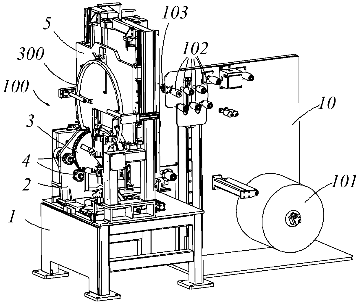
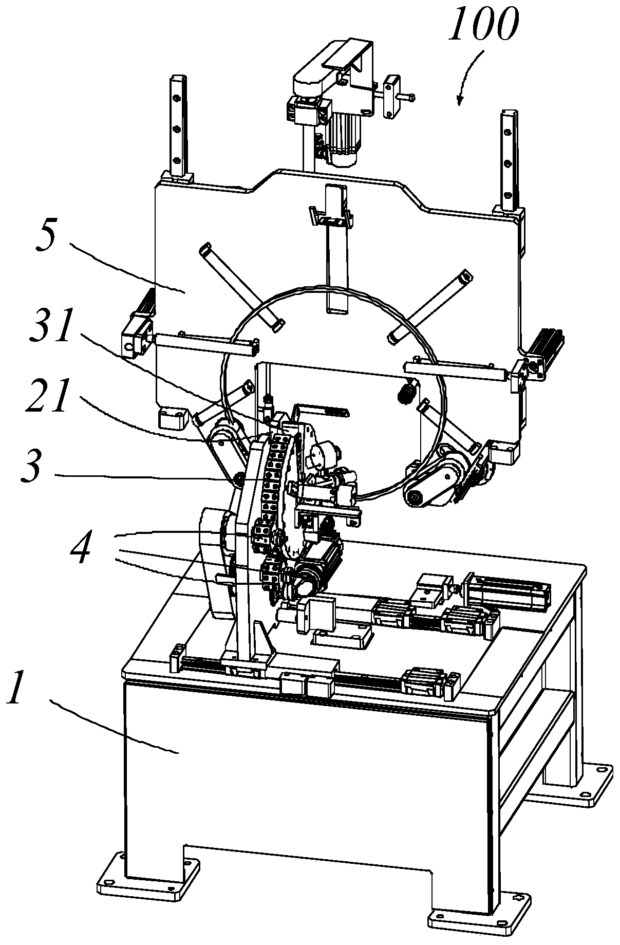
[0039] Such as Figure 1-Figure 7 , Figure 10-Figure 13 As shown, the present invention discloses a winding ring device 100 applied to a winding device, and the winding ring device 100 is used for spirally winding a strip 200 onto a bare bead 300 to form a bead. The winding ring device 100 includes a base 1 , a vertical plate 2 vertically arranged on the base 1 , a winding ring component 3 arranged on the vertical plate 2 , and a first driving mechanism 4 for driving the winding ring component 3 to rotate around its center. The wrapping ring part 3 is ring-shaped, and the wrapping ring part 3 is provided with a notch 31 , and the vertical plate 2 is provided with a notch 21 which basically coincides with the notch 31 . After the bare bead 300 enters the center of the winding ring component 3 from the notch 31 and the cutout 21 , the bare bead 300 and the winding ring component 3 cross each other, and the end surface of the bare bead 300 is perpendicular to the end surface of...

Embodiment 2

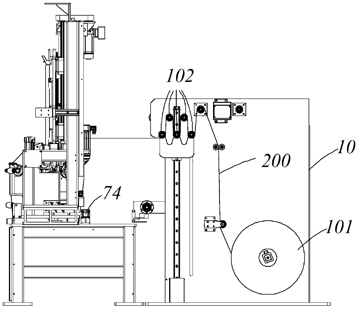
[0055] Such as Figure 1-13 As shown, the winding device in this embodiment includes all the components in Embodiment 1, and also includes a transmission mechanism 6 slidably arranged on the base 1 . Specifically, the transmission mechanism 6 is arranged on the base 1 through a guide rail slider mechanism 7, and the guide rail slider mechanism 7 includes two rows of guide rails 71 arranged on the base 1, a slider 72 slidingly arranged on each guide rail 71, The bottom plate 73 arranged on the two rows of sliders 72 and the driving cylinder 74 for driving the bottom plate 73 to move. The driving cylinder 74 can drive the bottom plate 73 to slide along the guide rail 71 , thereby driving the transmission mechanism 6 to move away from or close to the winding ring component 3 .

[0056] The transmission mechanism 6 includes a base plate 61 , a first driving source (not labeled) disposed on the base plate 61 , and a rotating component 62 disposed at a driving end of the first driv...

Embodiment 3

[0064] Such as Figure 1-13 As shown, this embodiment also provides a bead winding system with the winding device of Embodiment 2, and the bead winding system is used for fully automatic helical winding of the rubber strip 200 onto the bare bead 300 . The bead winding system includes a feeding device 10 , the winding device in Embodiment 2 above, and a cutting mechanism 20 for cutting a strip 200 .

[0065] The feeding device 10 includes a material roll 101, a plurality of storage rollers 102, an encoder 103 connected to the last storage roller 102 in the conveying direction, and a total drive source (not shown). The material roll 101 is discharged through multiple storage rollers. The material stored in the roller 102 is transferred to the winding ring device 100. After the bare bead 300 is placed on the winding ring device 100 driven by the second driving mechanism 5, the second driving mechanism 5 cooperates with the winding ring device 100. movement to helically wind the st...


PUM


Abstract

The invention provides a winding ring device. The winding ring device comprises a base; a winding ring part is arranged on the base, and provided with a notch part, a roller assembly and a damping assembly are arranged on the end wall of the winding ring part, and the roller assembly comprises a roller part wound with a strip; when the strip released by the roller part passes through the damping assembly and is wound on the bare tire bead, the strip is released; and the damping assembly applies constant resistance to the strip so that the strip is uniformly wound on the bare tire bead with constant tension. The invention also provides a winding device with the winding ring device and a tire bead winding system with the winding device, so that after the strip is wound on the bare tire bead,the strip has basically stable tension, the problems of bubbles and the like caused by unstable tension of the strip are avoided, and the winding quality is improved.

Description

technical field [0001] The invention relates to the field of tire production auxiliary equipment, in particular to a winding ring device, a winding device and a bead winding system. Background technique [0002] As a component of the tire, the bead supports the fastening force between the tire and the rim, maintains and seals the air pressure inside the tire, and plays an important role in the cushioning and adjustment safety of the sidewall of the tire. [0003] Generally, the bead includes a bare bead and a strip, wherein the bare bead is a structure formed by arranging single-core glued steel wires according to a specific cross-sectional shape, and its cross-sectional shape is usually roughly hexagonal. In the subsequent process, It is very important to maintain the cross-sectional hexagonal shape. The existing bead is to wind the strip onto the bare bead through the bead winding system, specifically, the winding ring part in the bead winding system is driven by the driv...

Claims


Application Information

Patent Timeline
Patent Type & Authority Applications(China)
IPC IPC(8): B29D30/50B29D30/46
CPCB29D30/46B29D30/50
Inventor 郑杰
Owner LINK-ASIA SMART TECH (SUZHOU) CO LTD
Why Eureka
Try Eureka