Aeration membrane device

A technology of aeration membrane and air intake pipe, applied in water aeration, sustainable biological treatment, water/sludge/sewage treatment, etc., can solve the problems of water flow level disorder, increase the oxygen content in water, and large air velocity, etc., to achieve Large aeration area, anti-corrosion, good effect

Active Publication Date: 2020-04-14
安徽普氏环保装备有限公司
View PDF5 Cites 0 Cited by
  • Summary
  • Abstract
  • Description
  • Claims
  • Application Information

AI Technical Summary

Problems solved by technology

[0002] In the process of sewage treatment, especially in the process of aerobic microbial treatment of sewage, it is necessary to inject a large amount of oxygen into the sewage, and at the same time discharge other gases such as methane and carbon dioxide produced by the sewage. The air membrane device inputs the compressed air into the water pipe, and then discharges it through the micropores on the aeration membrane device. The airflow velocity of the discharge is high, which can instantly burst the water, making the water flow level turbulent, and the water flow fully contacts with the air, increasing the water in the water. At the same time, the existing harmful gas is discharged. The height and position of the existing aeration membrane cannot be adjusted. When the sewage layer is deep, it is difficult for the aeration membrane device buried at the bottom to fully explode the water surface of the upper layer of sewage, and The air outlet head of the aeration membrane device is mostly flat, and the range of the upper and lower heights of the blasting is small. When the compressed air input is stopped, the sewage will flow back into the aeration membrane device through the micropores of the aeration membrane device and then flow into the pipeline. Harmful substances such as heavy metals can easily corrode the aeration membrane device and water pipes

Method used


Image

  • Aeration membrane device
  • Aeration membrane device
  • Aeration membrane device

Examples


Embodiment Construction

[0024] In order to make the technical means, creative features, goals and effects of the present invention easy to understand, the present invention will be further elaborated below in conjunction with specific embodiments.

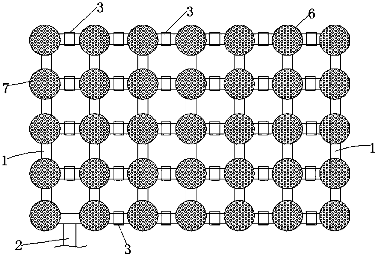
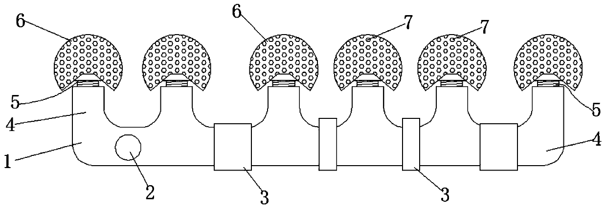
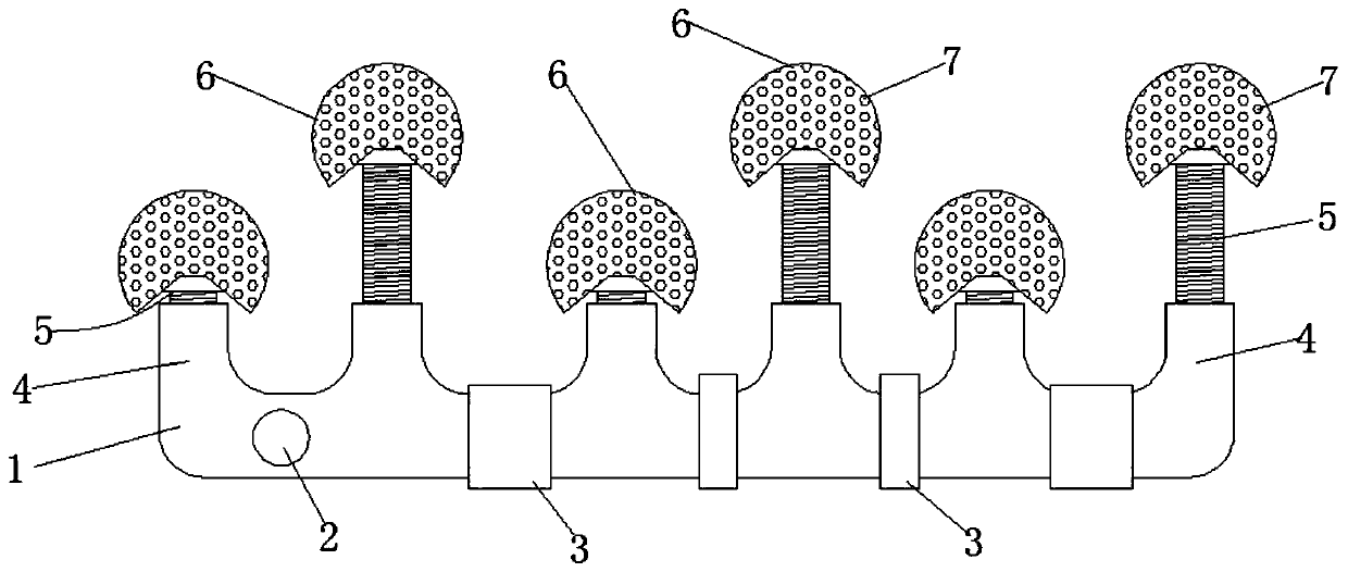
[0025] Such as Figure 1-6 As shown, an aeration membrane device includes a water pipe group 1, an air inlet pipe 2 is arranged on the water pipe group 1, and several fixing clips 3 are arranged on the water pipe group 1, and the fixing clips 3 fix the water pipe group 1 on the bottom of the sewage tank, On the water pipe group 1, there are also vertical connecting pipes 4 arranged at equal intervals. The tops of the vertical connecting pipes 4 are all provided with nozzles 6, and the nozzles 6 are provided with spray holes 7 at equal density. The compressed air passes through the intake pipe 2 and the water pipe group in turn. 1. The vertical connecting pipe 4, the nozzle 6 and the nozzle hole 7, the height of the nozzle 6 compared with the vertical conn...


PUM


Abstract

The invention discloses an aeration membrane device, which comprises a water pipe set, wherein a gas inlet pipe is arranged on the water pipe set, a plurality of fixing clamps are further arranged onthe water pipe set, vertical communicating pipes are further arranged on the water pipe set at equal intervals, spray heads are arranged at the top ends of the vertical communicating pipes, spray holes are formed in the spray heads at equal density, the heights of the spray heads relative to the vertical communicating pipes are adjustable, a sewage reflux preventing structure is further arranged in the spray heads and the vertical communicating pipes, and the upper surface of the spray head is a spherical surface. According to the invention, the spray head is a spherical surface, the aerationrange of the single spray head is large, the height of the spray head is adjustable, and the spray heads can be uniformly arranged on each sewage layer, so that the upper and lower aeration areas in the whole sewage uniformly and sufficiently contact air, the sewage reflux preventing structure can prevent the sewage from refluxing into the pipeline, the acid and alkali substances in the sewage canbe prevented from corroding the pipeline, microorganisms can be prevented from breeding on the inner wall of the pipeline, and the service life of the pipeline is greatly prolonged.

Description

technical field [0001] The invention relates to the field of sewage treatment process devices, in particular to an aeration membrane device. Background technique [0002] In the process of sewage treatment, especially in the process of aerobic microbial treatment of sewage, it is necessary to inject a large amount of oxygen into the sewage, and at the same time discharge other gases such as methane and carbon dioxide produced by the sewage. The air membrane device inputs the compressed air into the water pipe, and then discharges it through the micropores on the aeration membrane device. The airflow velocity of the discharge is high, which can instantly burst the water, making the water flow level turbulent, and the water flow fully contacts with the air, increasing the water in the water. At the same time, the existing harmful gas is discharged. The height and position of the existing aeration membrane cannot be adjusted. When the sewage layer is deep, it is difficult for t...

Claims


Application Information

Patent Timeline
Patent Type & Authority Applications(China)
IPC IPC(8): C02F3/02C02F7/00
CPCC02F3/02C02F7/00Y02W10/10
Inventor 张宁迁张锋孙震
Owner 安徽普氏环保装备有限公司
Why Eureka
Try Eureka