Efficient cooling industrial furnace

An industrial furnace, high-efficiency technology, applied in furnaces, heat treatment furnaces, manufacturing tools, etc., can solve the problems of poor uniformity and stability, short service life of the furnace, low cooling efficiency, etc., and achieve low cost, cost reduction, and cooling efficiency high effect

Inactive Publication Date: 2020-04-14
ZHEJIANG SHANGDING IND FURNACE
View PDF19 Cites 0 Cited by
  • Summary
  • Abstract
  • Description
  • Claims
  • Application Information

AI Technical Summary

Problems solved by technology

[0005] The object of the present invention is to address the deficiencies of the prior art and provide a high-efficiency cooling industrial furnace. By setting the heating assembly as hollow, the two ends of the heating tube are extended to the outside of the furnace body, and the heating tube is loaded Voltage, and a blower device is installed at one end of it, so that the furnace can use the high resistance of the heating tube to fully heat the workpiece when the furnace is heat-treating the workpiece, and after the heat treatment is completed, the blower device can be used to blow into the heating tube The wind forms an air flow in the heating tube to complete the heat exchange, which overcomes the problems of poor cooling uniformity and stability, low cooling efficiency, short service life of the furnace and high replacement cost in the existing method of directly cooling the furnace.

Method used


Image

  • Efficient cooling industrial furnace
  • Efficient cooling industrial furnace
  • Efficient cooling industrial furnace

Examples


Embodiment 1

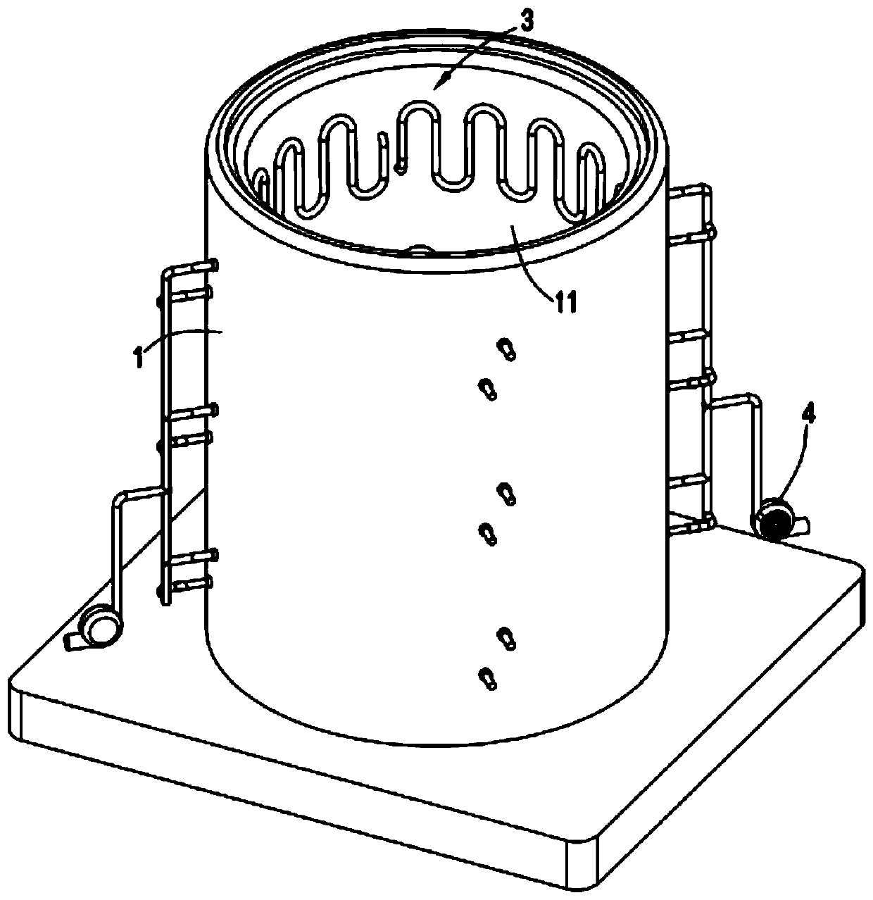
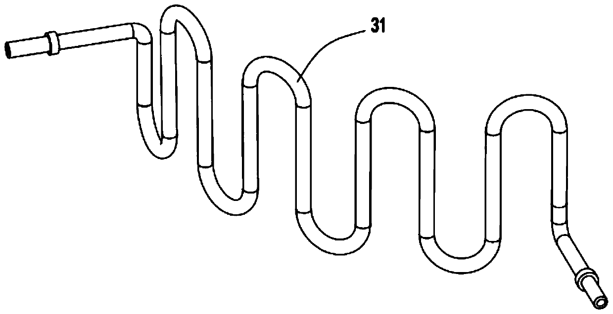
[0032] Such as Figure 1 to Figure 5 As shown, what is provided in this embodiment is a high-efficiency cooling industrial furnace, including a furnace body 1 and a furnace cover 2 arranged on the upper end of the furnace body 1 that can be opened and closed, and a heating assembly 3 is arranged on the inner wall of the furnace body 1 , the heating assembly 3 is provided in a hollow structure, and its two ends pass through the furnace wall 11 of the furnace body 1 and extend to the outside of the furnace body 1, and the two ends of the heating assembly 3 are respectively connected to positive and negative voltages, And one of the ends is the air inlet end, and the air inlet end is connected with the blower device 4 .

[0033] What is worth mentioning in the present invention is that by setting the heating assembly 3 as hollow, the two ends of its heating tube 31 are extended to the outside of the furnace body 1, and a voltage is applied to the heating tube 31, and one end The...

Embodiment 2

[0043] Such as figure 1As shown, the components that are the same as or corresponding to those in the first embodiment are marked with the corresponding reference numerals in the first embodiment. For the sake of simplicity, only the differences from the first embodiment will be described below. The difference between the second embodiment and the first embodiment is that further, the heating assembly 3 includes at least one heating tube 31 arranged along the circumferential direction of the furnace body 1 , and the heating tube 31 is arranged in a curved shape.

[0044] In this embodiment, by setting the heating assembly 3, it can be combined by a plurality of heating pipes 31, so that a plurality of heating pipes 31 can be evenly distributed according to needs, so that there are a plurality of air inlets and air outlets, so that further Improve the cooling rate of the furnace and shorten the time of the entire heat treatment process of the product.


PUM

PropertyMeasurementUnit
thicknessaaaaaaaaaa

Abstract

The invention relates to an efficient cooling industrial furnace. The efficient cooling industrial furnace comprises a furnace body and a furnace cover, wherein the furnace cover is arranged at the upper end of the furnace body and can be opened and closed. A heating component is arranged on the inner wall of the furnace body and is made of a hollow material, the two ends of the heating componentpenetrate through the furnace wall of the furnace body and extend to the outer portion of the furnace body, positive voltage and negative voltage are connected to the two ends of the heating componentrespectively, and one end of the heating component is connected with a blower device. The efficient cooling industrial furnace solves the problems that in the mode that temperature reducing and cooling are directly carried out on a furnace pipe, the cooling uniformity and the stability are poor, the cooling efficiency is low, the service life of the furnace pipe is short, and the replacement cotis high.

Description

technical field [0001] The invention relates to the technical field of industrial furnaces, in particular to a high-efficiency cooling industrial furnace. Background technique [0002] Industrial furnaces are used for heat treatment of workpieces. After the heat treatment is completed, it is necessary to cool down the furnace and then take out the workpieces. During the cooling process, the uniformity of cooling in various parts of the furnace and the efficiency of overall cooling are involved, and the inside of the furnace must be considered. The problem of aging replacement parts. [0003] A Chinese invention patent with the publication number CN105546992B discloses an industrial furnace with a liftable dust-absorbing furnace cover, including a furnace body, a furnace cover and a lifting mechanism for lifting the furnace cover. The inner wall of the furnace cover is formed with a semi-closed The top of the furnace cover is provided with a salt-adding channel, and the fixe...

Claims


Application Information

Patent Timeline
Patent Type & Authority Applications(China)
IPC IPC(8): C21D1/34C21D9/00
CPCC21D1/34C21D9/0062
Inventor 叶玉芳叶华健车磊祝守新
Owner ZHEJIANG SHANGDING IND FURNACE
Why Eureka
Try Eureka