
Improved ceiling fan lamp structure

A technology for ceiling fan lights and fans, applied in electromechanical devices, lighting and heating equipment, electrical components, etc., can solve the problems of very high requirements for blade installation process, large overall height, and difficult process, so as to avoid excessive stretching or compression. Failure, small overall height, avoid the effect of blade overlap

Pending Publication Date: 2020-04-14
ZHONGSHAN BAOSHAN ELECTRICAL APPLIANCE CO LTD
View PDF0 Cites 0 Cited by
  • Summary
  • Abstract
  • Description
  • Claims
  • Application Information

AI Technical Summary

Problems solved by technology

[0003] However, the above-mentioned ceiling fan lamp with hidden blades still has the following disadvantages: (1) when the blades are stored, that is, when the blades are returned (stored), each blade is surrounded by a circle on the edge of the upper surface of the chassis, Restricted by the circumference of the outer edge of the chassis, when the number of blades is large or the length of the blades is large, the adjacent blades will overlap from the beginning to the end. Therefore, in order to avoid collision (offset) between the overlapping blades during the retraction process, there is a It is made into two sections of high and low, or the blade is made into an upward extension from low to high. The blade is made into two sections of high and low. Collision, and the blades extend from low to high, which will cause the overall height to be large, especially the bottom of this ceiling fan lamp also includes the lamp part, so this ceiling fan lamp with too high height is not suitable for some lower floors (such as : Ordinary commodity building) room use
(2) When the blade is extended or retracted, it is realized by the rotation of the "rotation shaft" at the root of the blade, that is to say, the rotation of the entire blade is through the "rotation shaft" as the fulcrum, and the blade is prone to deviation due to installation differences (such as: drooping), it is easy to cause the blade to collide with the neighbor when it is retracted. Therefore, the requirements for the blade installation process are very high

Method used


Image

  • Improved ceiling fan lamp structure
  • Improved ceiling fan lamp structure
  • Improved ceiling fan lamp structure

Examples


Embodiment Construction

[0028] The present invention will be further described below in conjunction with drawings and embodiments.

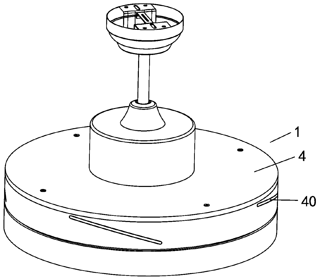
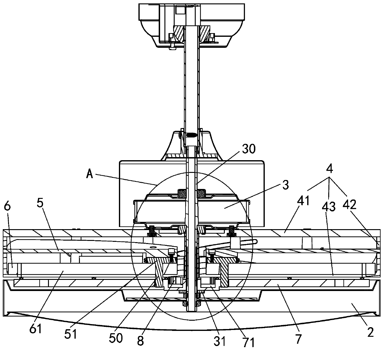
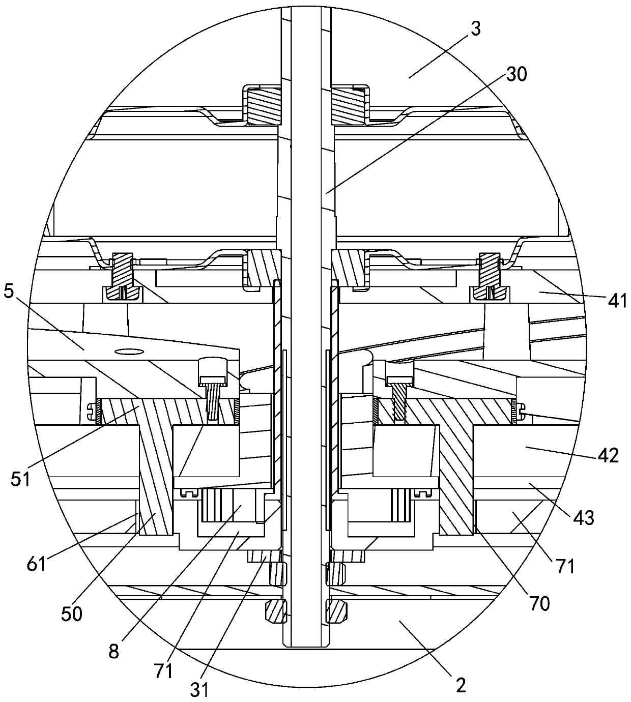
[0029] Such as Figure 1 to Figure 7 As shown, an improved structure of a ceiling fan lamp includes a fan part 1 and a lamp part 2. The fan part 1 is arranged on the upper part of the lamp part 2. The fan part 1 includes a motor 3, a blade storage cover 4, a blade 5, and a blade Guide rail 6 and synchronous disc 7, motor 3 is outer rotor motor 3, and blade storage cover 4 comprises top cover 41, annular sidewall 42 and rotating disk 43, and annular sidewall 42 is surrounded on the upper surface periphery of rotating disk 43, and rotating disk The center of 43 has shaft hole 44, has blade inlet and outlet hole 40 on the annular side wall 42, and the shape of blade inlet and outlet hole 40 is adapted to blade 5, and top cover 41 is fixed on the upper opening of annular side wall 42, and top cover 41 center openings There is a through hole 45, the motor 3 housing is fixed...


PUM


Abstract

The invention discloses an improved ceiling fan lamp structure. The improved ceiling fan lamp structure comprises a fan part and a lamp part; the fan part is arranged at the upper portion of the lamppart; the fan part comprises a motor, a rotating disc, blades and a blade guide rail; the fixed shaft of the motor penetrates through a shaft hole in the center of the rotating disc; the motor drivesthe rotating disc to rotate around the fixed shaft; the blade guide rail is fixed to the rotating disc in the radius direction of the rotating disc; and the blades are located on the blade guide railthrough sliding bases. When the motor drives the rotating disc to rotate around the fixed shaft, the blades slide outwards from the blade guide rail through the sliding bases under the action of a centrifugal force, so that at least part of each blade extends out of the rotating disc. The fan lamp has the advantages of low height and low blade installation process requirements.

Description

technical field [0001] The invention relates to the technical field of fan lamps, in particular to an improved structure of a ceiling fan lamp. Background technique [0002] The structure of the existing ceiling fan lamp includes a fan part and a lamp part. The fan part is arranged on the upper part of the lamp part. mechanism, the blades are set on the periphery of the upper surface of the chassis through the blade extension and reset mechanism, and the chassis is driven by the motor assembly; when the ceiling fan is working, the motor assembly drives the chassis to rotate, and the blades move along the blade extension and reset mechanism under the action of centrifugal force. At least a part of the blade protrudes (throws out) out of the chassis. When the ceiling fan stops working, the blade is retracted to the edge of the upper surface of the chassis by the reset force of the blade extension and reset mechanism; this traditional ceiling fan lamp is also called the blade (...

Claims


Application Information

Patent Timeline
IPC IPC(8): F04D25/08F04D29/32F04D29/38F04D29/34F21V33/00H02K7/14
CPCF04D25/088F04D29/325F04D29/34F04D29/388F21V33/0096H02K7/14
Inventor 谢刚
Owner ZHONGSHAN BAOSHAN ELECTRICAL APPLIANCE CO LTD
Features
  • Generate Ideas
  • Intellectual Property
  • Life Sciences
  • Materials
  • Tech Scout
  • Unparalleled Data Quality
  • Higher Quality Content
  • 60% Fewer Hallucinations
Learn More