Refrigeration pipeline assembly with defrosting function, evaporator and refrigeration equipment

A technology for refrigeration tubes and evaporators, which is applied in refrigeration components, evaporators/condensers, refrigerators, etc., and can solve the problems of outer wall insulation or protective layer wear and tear of heating parts, deformation or bending of aluminum tubes, and water storage that cannot be discharged outside and other problems, to achieve the effect of improving the cooling effect, fast defrosting speed, and tight fit

Pending Publication Date: 2020-04-14
刘易铭
View PDF1 Cites 0 Cited by
  • Summary
  • Abstract
  • Description
  • Claims
  • Application Information

AI Technical Summary

Problems solved by technology

Those skilled in the art analyze this structure by inserting the heating element in the channel. As we all know, there must be a gap between the outer wall of the heating element and the channel in order to insert the heating element. It will cause wear and tear damage to the insulation or protective layer of the outer wall of the heating element. Once damaged, there will be safety hazards; the numerical evaporation tube in this field is generally an aluminum tube, and the aluminum tube is easy to deform or bend. When the heating element is worn, once the aluminum tube deforms or The bending heating element will not be able to be inserted according to the expected channel, which will cause a lot of waste of aluminum tubes; in addition, due to the use of the insertion structure, there will be a certain amount of gaps, which will affect heat conduction on the one hand, and on the other hand, it will be easy in the gap after defrosting. Water is stored, and the stored water cannot be drained; after defrosting, it will freeze quickly after restarting the refrigeration

Method used


Image

  • Refrigeration pipeline assembly with defrosting function, evaporator and refrigeration equipment
  • Refrigeration pipeline assembly with defrosting function, evaporator and refrigeration equipment
  • Refrigeration pipeline assembly with defrosting function, evaporator and refrigeration equipment

Examples


Embodiment 1

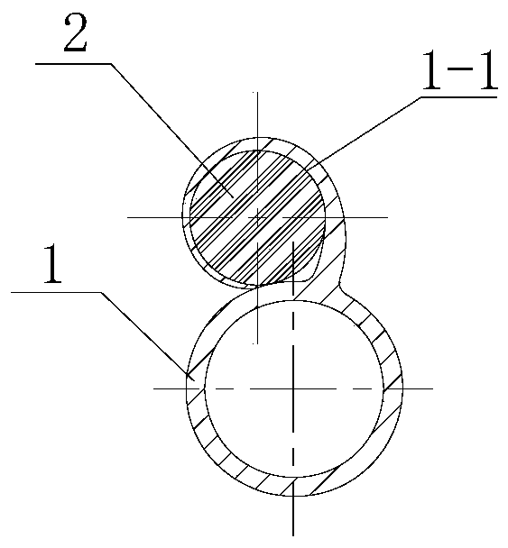
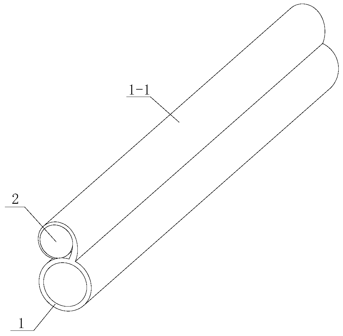
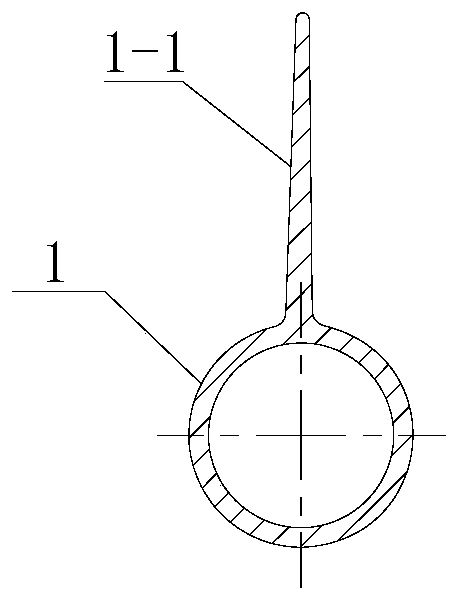
[0049] Example 1, see Figure 1 to Figure 3 ; A refrigeration pipeline assembly with a defrosting function, used in a refrigeration system, comprising a continuous refrigerant delivery pipe 1 with an inlet and an outlet, which is used to deliver a refrigerant medium; The heating pipe 2 is used for defrosting; the outer surface of the refrigerant delivery pipe is provided with a wrapping part 1-1 along the length direction of the refrigerant delivery pipe, and the wrapping part is integrally formed with the refrigerant delivery pipe; the wrapping part and the refrigerant delivery pipe are integrally formed. The thickness of the junction of the refrigerant delivery pipe is greater than the thickness of the extension of the wrapping part, and the thickness is linearly decreasing from the junction of the wrapping part and the refrigerant delivery pipe to the extension of the wrapping part; The heating tube is tightly wrapped to keep the electric heating tube in a static state rela...

Embodiment 2

[0051] Example 2: see Figure 4 to Figure 5 ; On the basis of Embodiment 1, an arc-shaped placement groove 1-2 equal to the outer diameter of the electric heating tube 2 is provided along the length direction on the refrigerant delivery pipe 1 near the root side of the wrapping part; The heating tube is placed in the arc-shaped placement slot, and the outer wall of the electric heating tube is attached to the outer wall of the placement slot. In this way, on the basis of Example 1, the contact area between the electric heating tube and the refrigerant delivery tube is increased, the heat exchange efficiency is improved, and the defrosting speed is accelerated. When the electric heating tube deviates, the production efficiency is improved. When the evaporator is wound, the seam is set to be slanted downward in order to facilitate drainage.

Embodiment 3

[0052] Example 3: See Figure 6 to Figure 7 ; A refrigeration pipeline assembly with a defrosting function, used in a refrigeration system, comprising a continuous refrigerant delivery pipe 1 with an inlet and an outlet, which is used to deliver a refrigerant medium; The heating pipe 2 is used for defrosting; the outer surface of the refrigerant conveying pipe is provided with two wrapping parts 1-1 along the length direction of the refrigerant conveying pipe, and the wrapping parts are integrally formed with the refrigerant conveying pipe; The height of the wrapping part is not less than the radius of the electric heating tube; the height of the two wrapping parts in this embodiment is greater than the radius of the electric heating tube, smaller than the diameter of the electric heating tube, and the upper ends of the two wrapping parts are not closed after wrapping; The heating tube is placed between the two wrapping parts, and the two wrapping parts are relatively bent to ...


PUM


Abstract

The invention discloses a refrigeration pipeline assembly with a defrosting function. The refrigeration pipeline assembly is used for a refrigeration system and comprises a refrigerant conveying pipewith a bending characteristic and an electric heating pipe which is static relative to the refrigerant conveying pipe; a wrapping part is arranged on the outer surface of the refrigerant conveying pipe in the length direction of the refrigerant conveying pipe, and the wrapping part and the refrigerant conveying pipe are integrally formed; the thickness of the joint part between the wrapping part and the refrigerant conveying pipe is larger than the thickness of the extension part of the wrapping part; and the electric heating pipe is tightly wrapped after being bent through the wrapping part,so that the electric heating pipe is kept in a static state relative to the refrigerant conveying pipe. By the adoption of the structure, efficient defrosting is achieved, the defrosting period is greatly prolonged, the refrigerating effect is improved, the defrosting frequency of an evaporator used in the low-temperature environment is reduced, and normal and efficient operation of the evaporatoris guaranteed; and the effective utilization rate of a refrigerating medium is high, the operation efficiency of the evaporator is improved, and energy conservation and environmental protection are better achieved.

Description

technical field [0001] The invention belongs to the technical field of refrigeration and defrosting, and in particular relates to a refrigeration pipeline assembly, an evaporator and refrigeration equipment with a defrosting function. Background technique [0002] With the development of refrigeration technology, frost-free refrigerators are becoming more and more popular. At present, the frost-free refrigerators on the market are generally air-cooled refrigerators. The principle of air-cooled refrigerators is to use air for cooling, and high-temperature air flows through the built-in When the evaporator (separated from the inner wall of the refrigerator), due to the high temperature of the air and the low temperature of the evaporator, the two directly exchange heat, the temperature of the air will decrease, and at the same time, the cold air will be blown into the refrigerator; the air-cooled refrigerator is through this The cold air is continuously circulated in the refri...

Claims


Application Information

Patent Timeline
Patent Type & Authority Applications(China)
IPC IPC(8): F28F1/24F28F1/36F28F19/00F25B39/02F25D21/08F25D23/00
CPCF25B39/02F25B2339/02F25D21/08F25D23/006F28F1/24F28F1/36F28F19/006
Inventor 刘易铭
Owner 刘易铭
Why Eureka
Try Eureka