
Laser radar detection device

A detection device and lidar technology, applied in measurement devices, radio wave measurement systems, instruments, etc., can solve problems such as image spot enlargement, light astigmatism, astigmatism, etc., to improve the quality and energy of the spot, and improve the light energy. , the effect of eliminating astigmatism

Active Publication Date: 2020-04-14
GUANGDONG BOZHILIN ROBOT CO LTD
View PDF4 Cites 3 Cited by
  • Summary
  • Abstract
  • Description
  • Claims
  • Application Information

AI Technical Summary

Problems solved by technology

At present, both the transmitting light path and the receiving light path of the lidar detection device pass through the radome. Due to the influence of the radome, the light will produce astigmatism. When reaching the detector, the radome has a divergent effect on the light, which makes the existing laser radar detection device have the problem of astigmatism, which makes the image spot larger and reduces the receiving efficiency of the detector in the laser radar

Method used


Image

  • Laser radar detection device
  • Laser radar detection device
  • Laser radar detection device

Examples


Embodiment Construction

[0024] In order to enable those skilled in the art to better understand the solutions of the present application, the technical solutions in the embodiments of the present application will be described clearly and completely in conjunction with the accompanying drawings in the embodiments of the present application. Obviously, the described embodiments are only a part of the embodiments of the present application, rather than all the embodiments. Based on the embodiments in this application, all other embodiments obtained by those skilled in the art without creative work are within the protection scope of this application.

[0025] The existing lidar detection device will have the problem of astigmatism, which will enlarge the image spot and reduce the receiving efficiency of the detector in the lidar. The meridian thin beam image point is on the main ray, and the sagittal thin beam image point is on the main ray and auxiliary ray. At the intersection of the axes, the axial dista...


PUM


Abstract

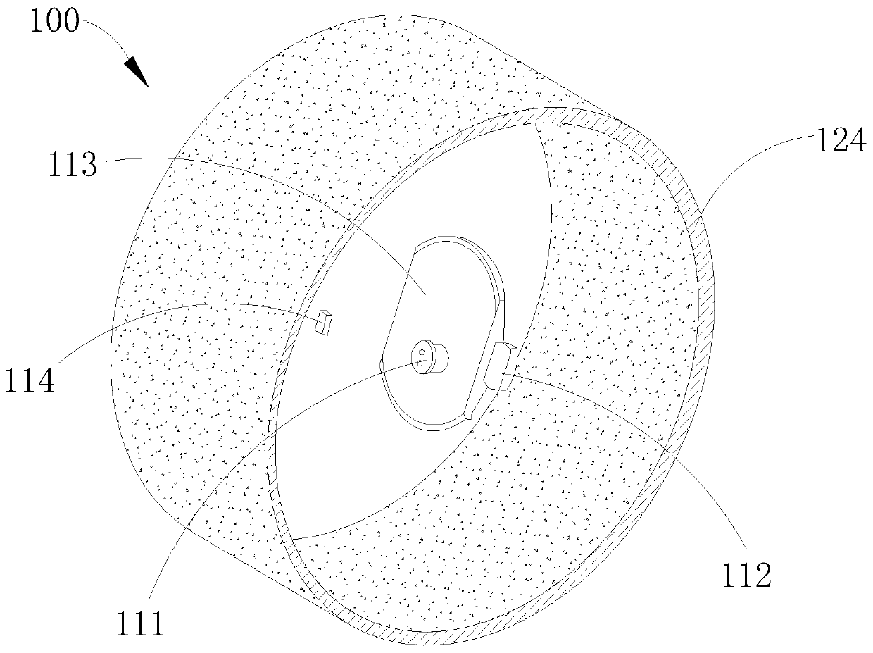
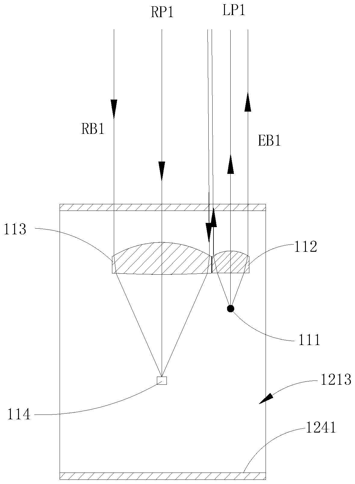
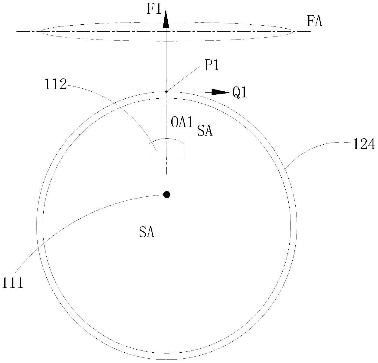
The invention provides a laser radar detection device. The device comprises a curved surface cover body, a laser, a first lens, a detector and a second lens. An emergent light beam of the laser is emitted to a measured object after passing through the first lens and the curved surface cover body in sequence to form a transmitting light path; the normal direction of the intersection point of the first optical axis of the first lens and the curved surface cover body coincides with the first optical axis; a reflected light beam reflected by the measured object sequentially passes through the cover body and the second lens and enters the detector to form a receiving optical path; and the normal direction of the intersection point of the second optical axis of the second lens and the curved surface cover body coincides with the second optical axis. According to the laser radar detection device provided by the invention, the first optical axis and the second optical axis are set to coincidewith the normal direction of the intersection point of each optical axis and the curved surface; the transmitting light path and the receiving light path are not influenced by the shape of the curvedsurface cover body, astigmatism of the transmitting light path and the receiving light path can be eliminated, the quality and the energy of light spots irradiated to a measured object by outgoing light beams are improved, and therefore, the light energy received by the detector and the detection performance of the laser radar are improved.

Description

Technical field [0001] This application relates to the field of lidar technology, specifically, to lidar detection devices. Background technique [0002] Lidar is a commonly used ranging sensor. Due to its advantages of high resolution and little interference from environmental factors, it is widely used in industrial fields, intelligent robots, automobiles and other fields. At present, both the transmitting light path and the receiving light path of the lidar detection device will pass through the radome, and the light will have astigmatism due to the influence of the radome. For example, when the detection light is reflected by an obstacle, it will return through the lidar cover When reaching the detector, the radome has a divergent effect on the light, so that the existing lidar detection device will have the problem of astigmatism, which makes the image spot larger and reduces the receiving efficiency of the detector in the lidar. Therefore, how to reduce the astigmatism of ...

Claims


Application Information

Patent Timeline
Patent Type & Authority Applications(China)
IPC IPC(8): G01S7/481G01S7/48G01S17/06
CPCG01S7/4802G01S7/481G01S17/06
Inventor 丁海鹏刘玉平丁思奇
Owner GUANGDONG BOZHILIN ROBOT CO LTD
Learn More