
Battery heating control device and heating control method

A heating control device and heating control technology, which are applied in battery temperature control, secondary batteries, circuits, etc., can solve the problems of inability to realize the charging function, poor consistency, and large differences.

Pending Publication Date: 2020-04-14
SHANGHAI PYLON TECH CO LTD
View PDF3 Cites 6 Cited by
  • Summary
  • Abstract
  • Description
  • Claims
  • Application Information

AI Technical Summary

Problems solved by technology

[0002] Batteries such as lithium iron phosphate batteries cannot be charged at low temperatures. For example, after charging a lithium iron phosphate battery, the battery voltage will immediately jump to the full charge voltage at room temperature, and the charging current is also very small, which will easily cause battery damage and cannot be recovered.
[0003] In order to solve the above problems, at present, the battery cell can be heated before charging the battery, and the battery can be charged after reaching the temperature that allows the battery to be charged. The traditional heating method is generally to install heating devices on both sides of the battery. However, due to the large difference in the distance between the heating device and the different cells in the battery, the consistency of the temperature of the cells is poor, and the maximum temperature difference between the cells can even reach 25 ° C, resulting in the battery being used for a period of time. The consistency of the voltage between the cells is getting worse and worse, and the power of the battery depends on the cell with the lowest voltage, which leads to a gradual decrease in the available capacity of the battery and seriously affects the service life of the battery

Method used


Image

  • Battery heating control device and heating control method
  • Battery heating control device and heating control method
  • Battery heating control device and heating control method

Examples


Embodiment Construction

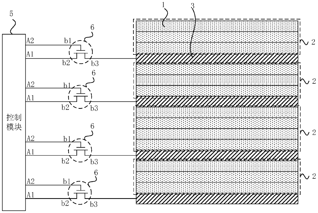
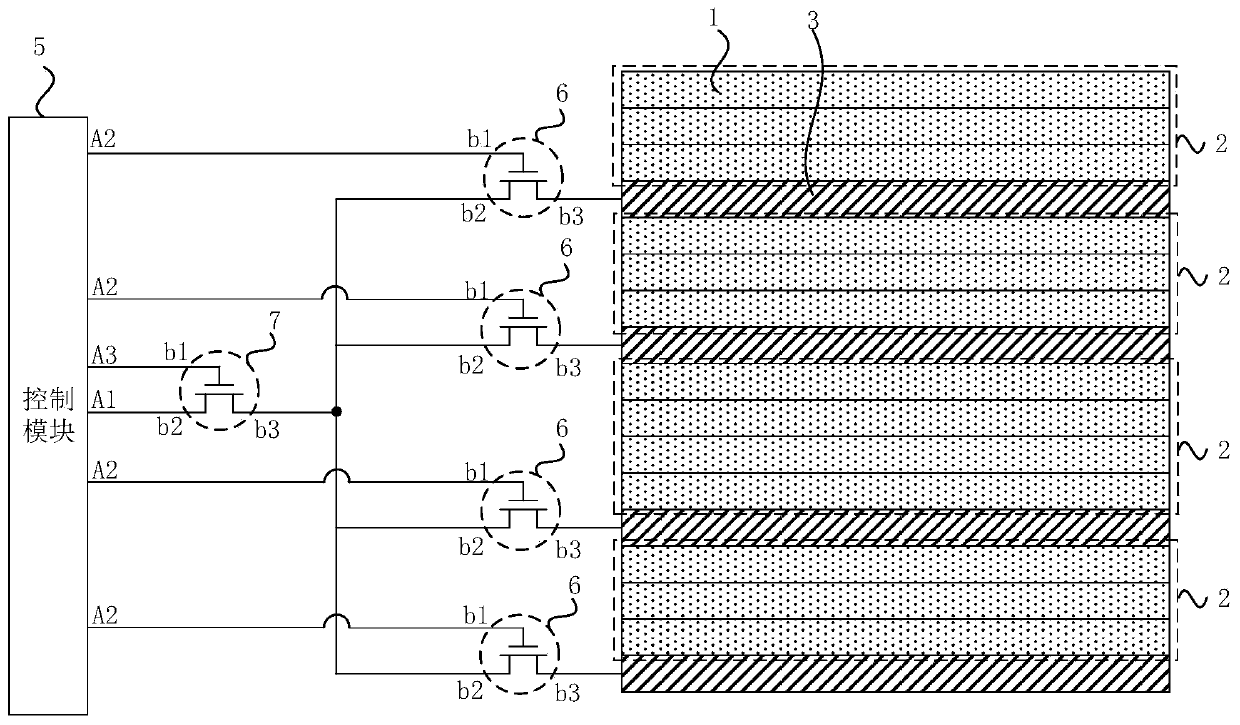
[0044]The present invention will be further described in detail below in conjunction with the accompanying drawings and embodiments. It should be understood that the specific embodiments described here are only used to explain the present invention, but not to limit the present invention. In addition, it should be noted that, for the convenience of description, only some structures related to the present invention are shown in the drawings but not all structures. Throughout this specification, the same or similar reference numerals represent the same or similar structures, elements or processes. It should be noted that, in the case of no conflict, the embodiments in the present application and the features in the embodiments can be combined with each other.

[0045] figure 1 It is a schematic structural diagram of a battery heating control device provided by an embodiment of the present invention. Such as figure 1 As shown, the battery includes a plurality of stacked batte...


PUM


Abstract

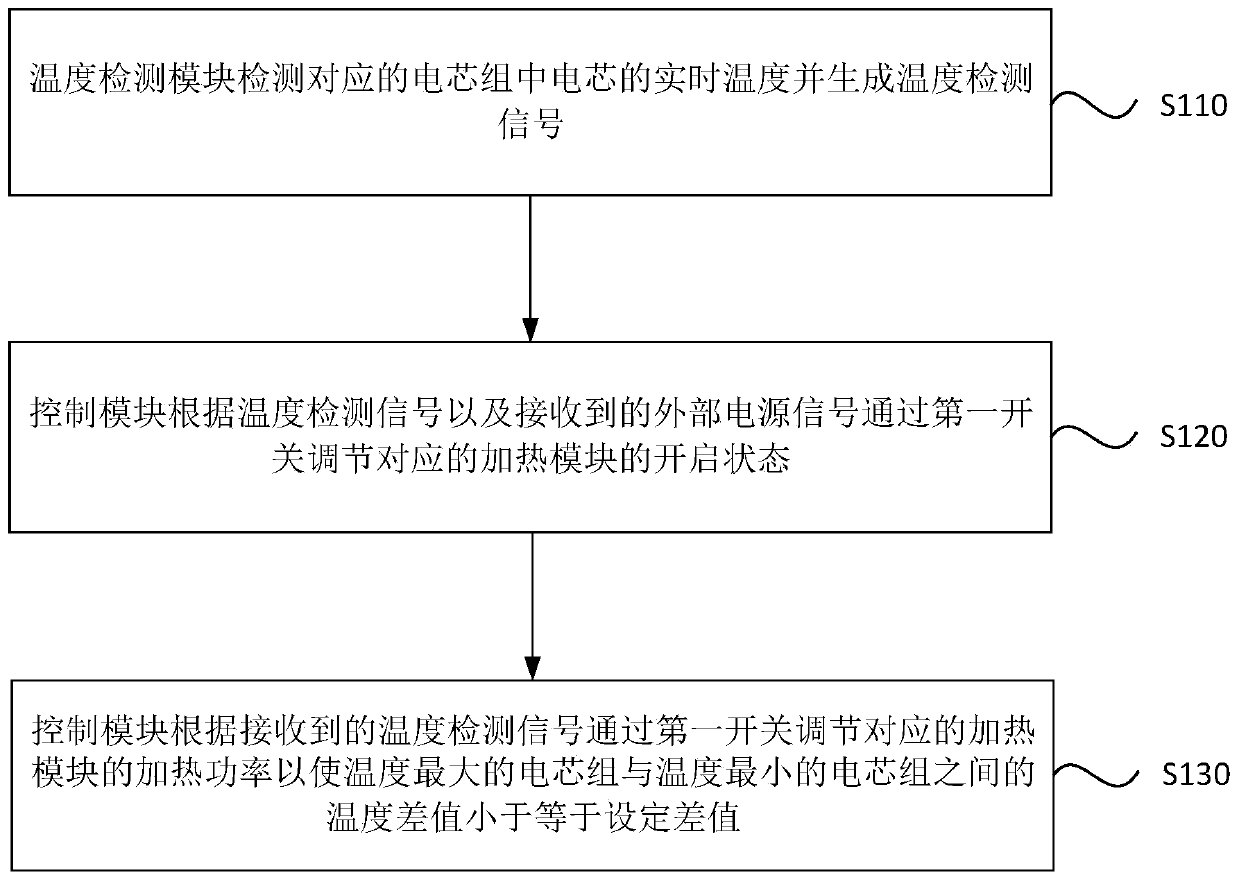
The invention discloses a battery heating control device and a heating control method. The heating control device comprises at least three heating modules, at least three temperature detection modules, a control module and first switches, wherein the heating modules are in one-to-one correspondence with battery cell groups, and the heating modules heat battery cells in the corresponding battery cell groups when being started; the temperature detection modules are in one-to-one correspondence with the battery cell groups, and the temperature detection modules are used for detecting a real-timetemperature of the battery cells in the corresponding battery cell groups and generating temperature detection signals; the first switches are arranged corresponding to the heating modules; and the control module adjusts a starting state of the corresponding heating modules through the first switches according to the temperature detection signals and a received external power supply signal, and adjusts heating power of the corresponding heating modules through the first switches according to the received temperature detection signals so as to make a temperature difference value between the battery cell group with a maximum temperature and the battery cell group with a minimum temperature be less than or equal to a set difference value. Through the technical scheme of the invention, consistency of the battery cell temperatures is improved.

Description

technical field [0001] Embodiments of the present invention relate to the technical field of batteries, and in particular, to a battery heating control device and a heating control method thereof. Background technique [0002] Batteries such as lithium iron phosphate batteries cannot be charged at low temperatures. For example, after charging a lithium iron phosphate battery, the battery voltage will immediately jump to the full charge voltage at room temperature, and the charging current is also very small, which will easily cause battery damage and cannot be recovered. . [0003] In order to solve the above problems, at present, the battery cell can be heated before charging the battery, and the battery can be charged after reaching the temperature that allows the battery to be charged. The traditional heating method is generally to install heating devices on both sides of the battery. However, due to the large difference in the distance between the heating device and the...

Claims


Application Information

Patent Timeline
IPC IPC(8): H01M10/615H01M10/617H01M10/63H01M10/635
CPCH01M10/615H01M10/617H01M10/63H01M10/635Y02E60/10
Inventor 宋慰军曹笑吟王红星姚斌
Owner SHANGHAI PYLON TECH CO LTD
Learn More