
Printed board mounting die and method

A printed board and mounting technology, which is used in printed circuit manufacturing, printed circuits, and electrical components to assemble printed circuits. It can solve the problems of low mounting efficiency and reliability of printed boards, and improve the quality and Placement efficiency, solving stress effects and waste of resources, improving work efficiency

Inactive Publication Date: 2020-04-14
BEIJING INST OF RADIO METROLOGY & MEASUREMENT
View PDF5 Cites 6 Cited by
  • Summary
  • Abstract
  • Description
  • Claims
  • Application Information

AI Technical Summary

Problems solved by technology

[0003] This application proposes a printed board mounting mold and method to solve the problem of low efficiency and reliability of printed board mounting

Method used


Image

  • Printed board mounting die and method
  • Printed board mounting die and method
  • Printed board mounting die and method

Examples


Embodiment Construction

[0038] In order to make the purpose, technical solution and advantages of the present application clearer, the technical solution of the present application will be clearly and completely described below in conjunction with specific embodiments of the present application and corresponding drawings. Apparently, the described embodiments are only some of the embodiments of the present application, rather than all the embodiments. Based on the embodiments in this application, all other embodiments obtained by persons of ordinary skill in the art without making creative efforts belong to the scope of protection of this application.

[0039] The technical solutions provided by various embodiments of the present application will be described in detail below in conjunction with the accompanying drawings.

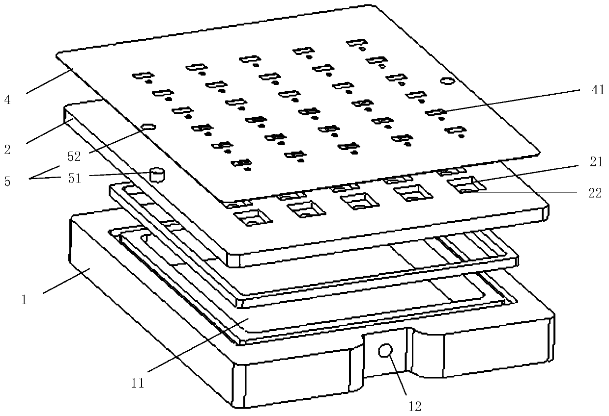
[0040] figure 1 It is a schematic diagram of an embodiment of the device.

[0041] The embodiment of the present application proposes a printed board mounting mold, including a c...


PUM


Abstract

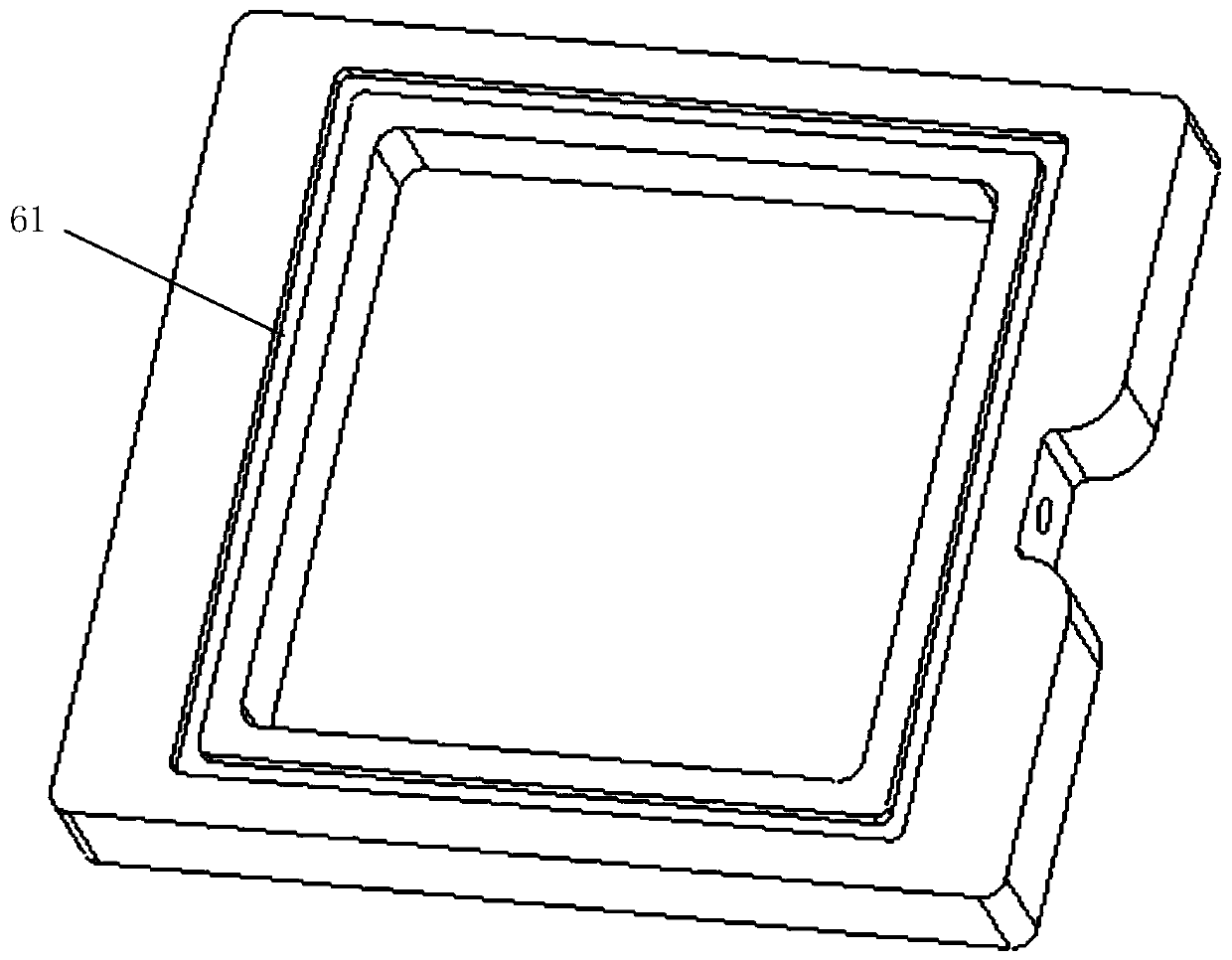
The invention discloses a printed board mounting die and method. The die comprises a base plate, a carrying plate, a template and a positioning plate. The base plate comprises a cavity with an upwardopening, and a space in the cavity is connected with the outside of the base plate through air holes in the base plate. The carrying plate covers the opening of the cavity and is in sealing contact with the base plate. A groove is formed in a surface of the carrying plate and used for placing a printed board, and a through hole is formed in a bottom of the groove and is connected with the cavity.The template comprises hollow points and is used for printing a soldering paste on the printed board. And the positioning plate comprises a mounting hole for mounting a component on the printed board.The invention further provides a printed board mounting method applying the device. According to the scheme, problems of low printed board mounting efficiency and reliability are solved.

Description

technical field [0001] The present application relates to the field of electronic technology, in particular to a printed board mounting mold and a method for mounting printed board components. Background technique [0002] Reflow soldering is a welding technology for microelectronic products. The welding process is mainly as follows: first, apply an appropriate amount of solder paste on the pad of the printed board, then paste the components on the corresponding position, and then place the printed circuit board with the components The board is put into the reflow soldering equipment for reflow soldering. At present, when surface mounting small-sized printed boards, a large printed board composed of multiple small printed boards is used for screen printing, and then the components are mounted for reflow soldering, and finally all the small printed boards are printed. The way the board is broken apart. This method has three major disadvantages. One is that the small-sized p...

Claims


Application Information

Patent Timeline
Patent Type & Authority Applications(China)
IPC IPC(8): H05K3/34H05K3/12
CPCH05K3/1216H05K3/341H05K2203/0165
Inventor 哈斯图亚郑文强段友峰崔巍刘小光
Owner BEIJING INST OF RADIO METROLOGY & MEASUREMENT
Learn More