Seeding machine

A planter and rack technology, which is applied to fertilizers, planting equipment, planting methods, applications, etc., can solve the problems of complex structure of planters and poor passability of tools and the like.

Pending Publication Date: 2020-04-17
黑龙江丰沃非凡农业科技发展有限公司
View PDF0 Cites 4 Cited by
  • Summary
  • Abstract
  • Description
  • Claims
  • Application Information

AI Technical Summary

Problems solved by technology

[0003] For this reason, the embodiment of the present invention provides a seeder to solve the problem

Method used


Image

  • Seeding machine
  • Seeding machine
  • Seeding machine

Examples


Embodiment 1

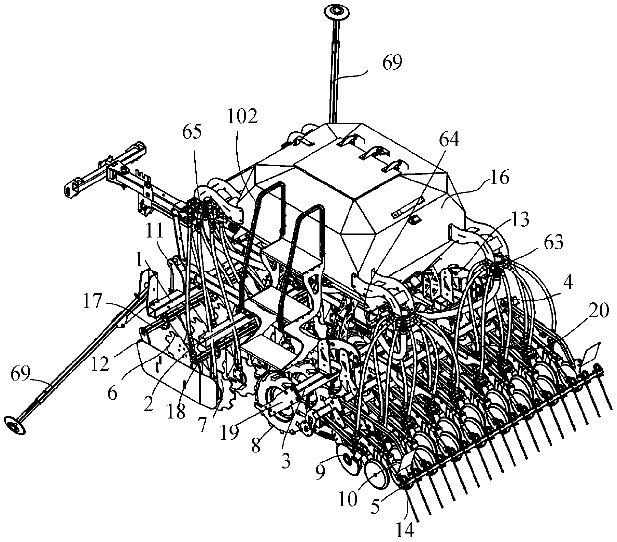
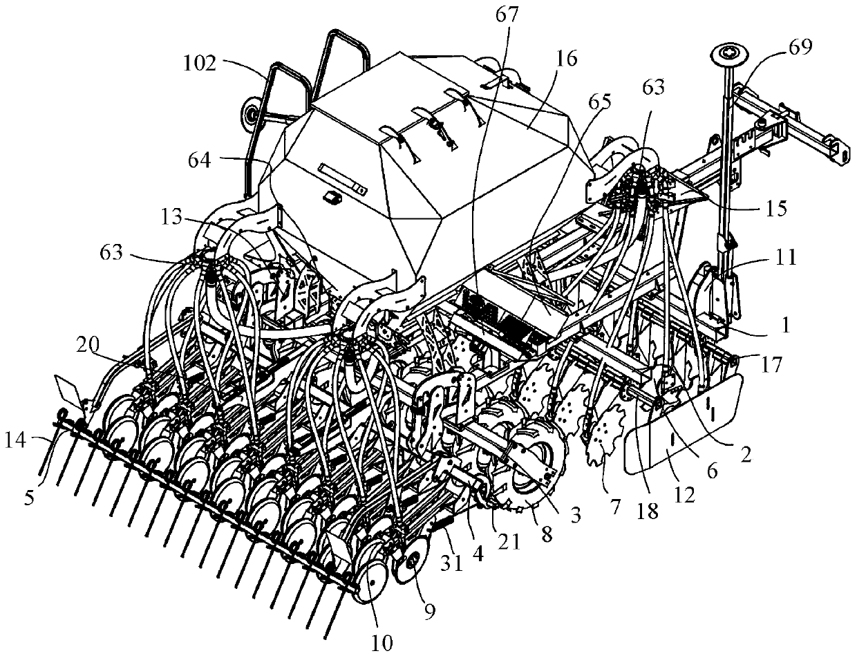
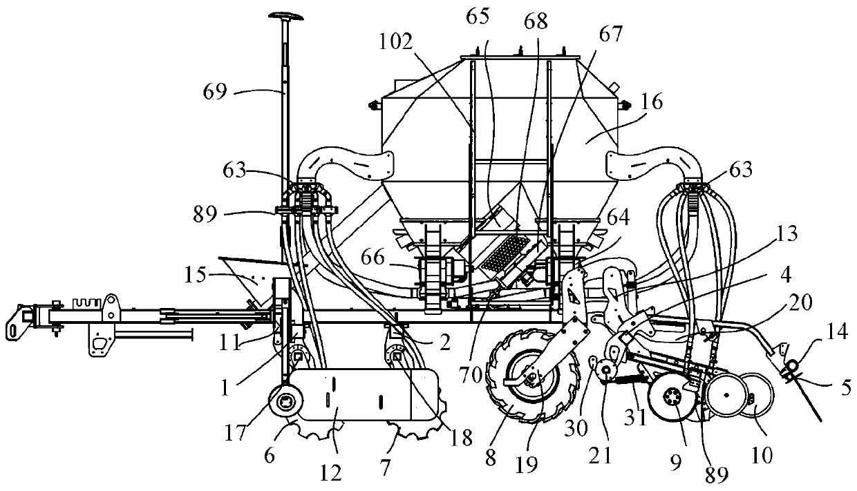
[0037] Such as Figure 1 to Figure 5 As shown, a planter in this embodiment includes a frame, a fertilizing monomer assembly, a walking suppression assembly, a seeding monomer assembly, a soil covering device, a selective material lifting mechanism 15, a seed fertilizer box 16, and a planter. Fertilizer discharge system and liner 69; the front end of the frame is provided with a traction frame, and the rear side of the frame is located at the traction frame and is successively provided with a fertilization monomer assembly, a walking suppression assembly, a seeding monomer assembly and a soil covering device. The two sides of the front end of the frame are respectively provided with markers 69; the top of the frame is fixed with a kind of fertilizer box 16, and one end of the selective material lifting mechanism 15 is fixed on the front bottom of the kind of fertilizer box 16, and the other end extends into the kind of fertilizer box 16, the selective material lifting mechanis...

Embodiment 2

[0040] Figure 1 to Figure 17 As shown, a planter in this embodiment includes all the technical features in Embodiment 1. In addition, the fertilization unit assembly includes a first beam 1, a second beam 2, a plurality of first fertilization units Body 6, a plurality of second fertilization monomers 7, fertilization pressure regulating device 11 and linkage 12; the walking suppression assembly includes a third crossbeam 3, a plurality of walking suppression wheels 8 and wheel arms 19; the sowing monomer assembly includes The fourth crossbeam 4, a plurality of first sowing units 9, a plurality of second sowing units 10 and a planting pressure regulating device 13; the soil covering device includes the fifth crossbeam 5 and a plurality of spring teeth 14; the first crossbeam 1, the second The beam 2, the third beam 3, the fourth beam 4 and the fifth beam 5 are arranged in parallel at intervals from front to back. The first beam 1, the second beam 2 and the third beam 3 are all...

Embodiment 3

[0043] Figure 1 to Figure 17 As shown, a planter in this embodiment includes all the technical features in Embodiment 2. In addition, the fertilization unit assembly also includes a shock absorber 41, a first rotating beam 17 and a second rotating beam 18. The fertilization pressure regulating device 11 includes a support plate 22, a fertilization hydraulic cylinder 23 and a fertilization connection ear 24; the shock absorber 41, the first rotating beam 17 and the second rotating beam 18 are square steel pipe structures, and the first fertilizing monomer 6 The shock absorber 41 is connected to the first rotating beam 17 through the shock absorber 41. The shock absorber 41 on the first fertilization unit 6 is sleeved on the first rotate beam 17. The second fertilization unit 7 is connected to the first rotating beam 17 through the shock absorber 41. On the two rotating crossbeams 18, the shock absorber 41 on the second fertilization monomer 7 is sleeved on the second rotating ...


PUM


Abstract

The invention discloses a seeding machine. A fertilization monomer assembly, a walking and pressing assembly, a seeding monomer assembly and a soil covering device are sequentially arranged in the position, located on the rear side of a traction frame, of a machine frame, and scribers are arranged on two sides of the front end of the machine frame; a seed and fertilizer box is fixed on the machineframe, one end of a selective material lifting mechanism is arranged in the front below the seed and fertilizer box, and the other end extends into the seed and fertilizer box for conveying a fertilizer and seeds into a fertilizer cavity and a seed cavity of the seed and fertilizer box, respectively; and the input opening of a seed fertilizer discharge system communicates with the seed and fertilizer box, and the output opening respectively communicates with the fertilization monomer assembly and the seeding monomer assembly for pneumatically conveying the fertilizer to the fertilization monomer assembly and conveying the seeds to the seeding monomer assembly. The seeding machine aims to solve the problem that a seeding machine of drill seeding operation in the prior art has a complicatedstructure and poor machine and tool passability, and has the following effects: the soil structure of loose rows and close rows arranged at intervals is formed after seeding, the stable yield is ensured despite drought or excessive rain, the crop yield is enhanced, the manufacturing costs of the machine and tools are low, and the seeding machine has strong adaptability.

Description

technical field [0001] The embodiment of the present invention relates to the technical field of agricultural machinery, in particular to a seeder. Background technique [0002] In the prior art, the seeder is an important equipment in the agricultural production process. During the operation of the seeder, it needs to face complex soil surface conditions. The efficiency of the sowing operation has become the focus of increasing attention in the field of agricultural machinery. The seeder used in the grain drill operation Among them, multi-row fertilization and multi-row sowing are required to ensure uniform pressure on the ground, and seed meters and fertilizer dischargers are required to discharge uniform seed flow and fertilizer flow. Generally, seed drills are large in size, and the positions of seed boxes and fertilizer boxes It is relatively high, and it takes a lot of labor to manually add materials to the seed box and fertilizer box during the operation process. The ...

Claims


Application Information

Patent Timeline
IPC IPC(8): A01C7/06A01C5/06
CPCA01C5/064A01C5/066A01C5/068A01C7/06
Inventor 于江龙郝文超孟祥禹伍鑫杨慧超
Owner 黑龙江丰沃非凡农业科技发展有限公司
Why Eureka
Try Eureka