Orange peeling device

A peeling device and orange peeling technology, which is applied in the peeling of vegetables or fruits, food science, application, etc., can solve the problems of low efficiency, failure to ensure that the same standard of orange peeling is peeled off, and many defective products. The effect of saving energy, reducing defective products, and ensuring integrity

Active Publication Date: 2020-04-17
重庆天邦食品有限公司
8 Cites 0 Cited by

AI-Extracted Technical Summary

Problems solved by technology

The method of manual peeling is not only inefficient, but also cannot guarantee that each piece of...

Method used

In like manner, after the orange enters the peeling mechanism 500, the peeling drive wheel 630 rotates forward, and drives the second strip tooth 513 to move upwards, until the upper peeling disc 521 and the lower peeling disc 522 hold the orange tightly, and the rotary cutting When the transmission wheel 620 forwardly rotates one circle and pauses, the second switch piece 525 moves to the second rotating motor 527 at this time, and the second switch piece 525 is offset against the positive pole piece and the negative pole piece of the second rotating motor 527 at the same time, so that the second The circuit of the rotary motor 527 is connected, the second rotary motor 527 motor drives the transmission rod 526 to rotate, and the transmission rod 526 drives the driving wheel group and the lower driving wheel 529 to rotate, and then drives the upper driven wheel 523 and the lower driven wheel 524 along the opposite direction rotate. In this way...

Abstract

The invention discloses an orange peeling device, comprising a frame, a conveying mechanism, a processing chamber, a rotary cutting mechanism, a peeling mechanism and a main driving assembly, whereinthe conveying mechanism is arranged at the front end of the frame and the tail end of the conveying mechanism in the processing chamber; the rotary cutting mechanism comprises a first enclasping assembly, a rotating assembly and a cutter; the conveying mechanism can convey an individual orange on the conveying mechanism to the first enclasping assembly; the first enclasping assembly can enclasp the conveyed orange; the rotating assembly is arranged on the first enclasping assembly; the rotating assembly can be started and drive the orange to rotate after enclasping of the first enclasping assembly; the cutter is arranged on the frame; orange slices of the orange on the rotating assembly can be cut into an upper hemisphere and a lower hemisphere in the rotating process of the rotating assembly; and the peeling mechanism can separate the two cut hemispheres from pulp in a rotating mode. According to the orange peeling device, orange peel and the pulp can be quickly separated, and the integrity of the orange peel can be well guaranteed.

Application Domain

Vegetable peeling

Technology Topic

Agricultural engineeringStructural engineering +1

Image

  • Orange peeling device
  • Orange peeling device
  • Orange peeling device

Examples

  • Experimental program(1)

Example Embodiment

[0025] The embodiments of the technical solution of the present invention will be described in detail below in conjunction with the accompanying drawings. The following embodiments are only used to explain the technical solutions of the present invention more clearly, and therefore are only used as examples, and cannot be used to limit the protection scope of the present invention.
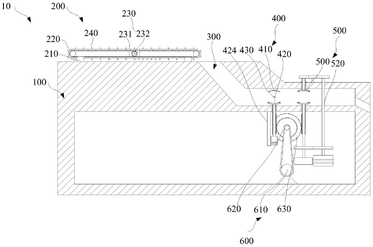
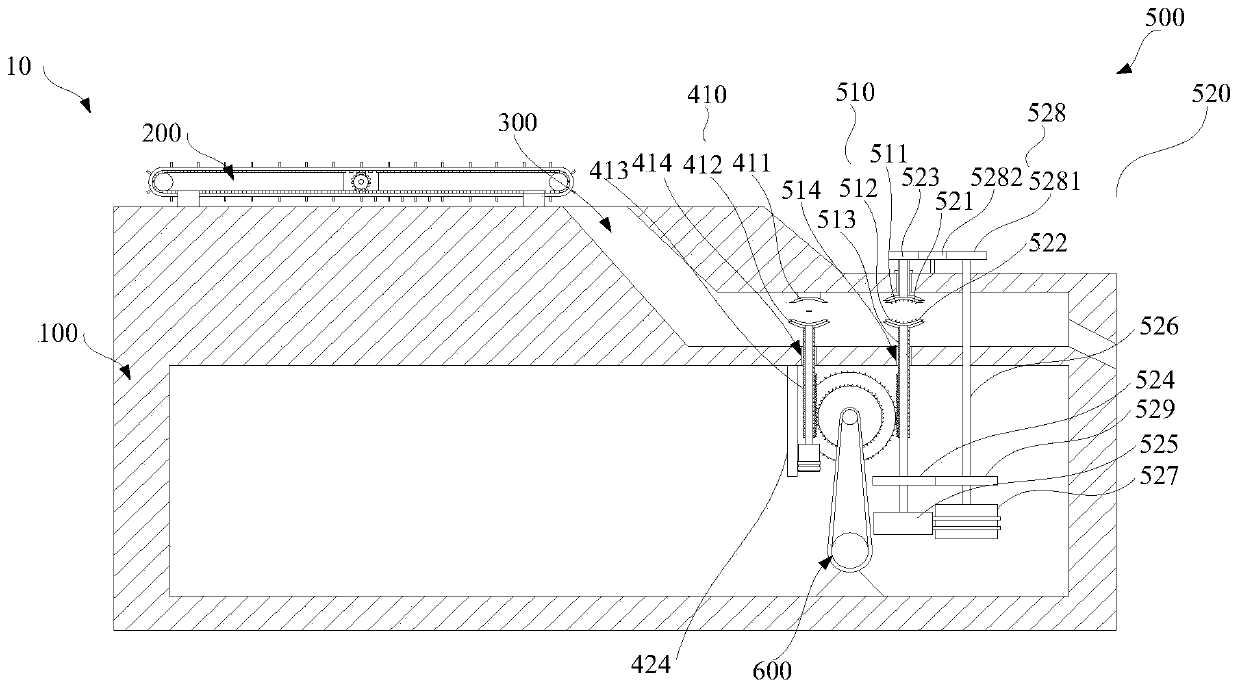
[0026] Such as Figure 1 to Figure 3 As shown, this embodiment provides an orange peel peeling device 10, which includes a frame 100, a conveying mechanism 200, a processing chamber 300, a rotary cutting mechanism 400, a peeling mechanism 500, and a total drive assembly 600 for removing orange peels from oranges. On peeling.
[0027] Specifically, the frame 100 is used to support the entire device. The conveying mechanism 200 is arranged at the front end of the frame 100, and the conveying mechanism 200 is used to convey oranges. The processing chamber 300 is located at the rear end of the conveying mechanism 200, and an outlet is provided at the rear end of the processing chamber 300 away from the conveying mechanism 200. The rotary cutting mechanism 400 includes a first holding component 410, a rotating component 420 and a cutter 430. The first holding assembly 410 is disposed in the processing chamber 300 and close to the conveying mechanism 200. The conveying mechanism 200 can individually convey the oranges thereon to the first holding assembly 410. The first holding component 410 can hold the transported orange tightly. The rotating assembly 420 is disposed on the first holding and clamping assembly 410. After the first holding assembly 410 is held tightly, the rotating assembly 420 can be activated and drive the orange to rotate. The cutting knife 430 is set on the frame 100 and extends into the rotating assembly 420 to insert the orange peel of the orange. During the rotation of the rotating assembly 420, the orange piece held by the rotating assembly 420 can be cut into two upper and lower hemispheres. The peeling mechanism 500 is arranged in the processing chamber 300 and located on the side away from the conveying mechanism 200. The peeling mechanism 500 can separate the two hemispheres after cutting from the pulp. The overall driving assembly 600 includes a servo motor 610, a rotary cutting transmission wheel 620 and a peeling transmission wheel 630. The servo motor 610 is an intermittent bidirectional rotating motor. The power output shaft of the servo motor 610 is provided with a rotary cutting transmission wheel 620 and a peeling transmission wheel 630 at intervals. The rotary cutting transmission wheel 620 is rotatably connected with the first holding component 410. The peeling transmission wheel 630 is rotatably connected with the peeling mechanism 500. The overall driving assembly 600 can simultaneously drive the first holding assembly 410 to hold or separate and drive the peeling mechanism 500 to twist to separate the peel and the pulp.
[0028] In this embodiment, the servo motor 610 is programmed and adjusted, so that after the servo motor 610 rotates forward for a circle, it can pause for a certain period of time and return to the original position after rotating in the reverse direction for a period of time, so that the movement will repeat. When in use, the conveying mechanism 200 and the overall driving assembly 600 are activated at the same time. The conveying mechanism 200 transports the orange to the processing chamber 300. Driven by the servo motor 610, the rotary cutting drive wheel 620 drives the first holding and tightening assembly 410 to close and hold the orange. After the first holding assembly 410 is held tightly, it can start the rotating assembly 420 and drive the orange to rotate. During the pause after one rotation, the cutter 430 can rotate the orange peel into two hemispheres. After the first holding component 410 is driven to separate, the orange is pushed by the subsequently transported orange to peel off the mechanism 500, and the peeling mechanism 500 is twisted to separate the peel from the pulp.
[0029] The conveying mechanism 200 includes a supporting frame 210, a conveyor belt 220 and a rotating power source 230. The support frame 210 includes a support column and a support plate. There are four supporting columns, arranged in pairs of two. The supporting plate is horizontally arranged on the supporting column. The conveyor belt 220 is slidably sleeved on the support plate. The oranges rest on the conveyor belt 220. The edge of the conveyor belt 220 is provided with a plurality of first teeth at intervals along its length direction. The rotation power source 230 includes a driving gear 231 and a driving motor 232. The driving gear 231 is laterally arranged on the support plate through a rotating shaft, and the driving gear 231 can mesh with the first tooth. A driving motor 232 is provided on the driving gear 231. When in use, the oranges can be placed on the conveyor belt 220 sequentially, and the oranges can be transported to the processing chamber 300 through the conveyor belt for processing. In this embodiment, the conveyor belt 220 is provided with a plurality of partitions 240 at intervals along the conveying direction. When placing oranges, place an orange next to each partition 240, and the oranges can be ordered individually.
[0030] The first holding assembly 410 includes a first upper clamping plate 411, a first lower clamping plate 412 and first bar-shaped teeth 413. The first upper clamping plate 411 is opposite to the first lower clamping plate 412. The first upper clamping plate 411 is provided at the top end of the processing chamber 300. The first lower clamping plate 412 is provided at the bottom of the processing chamber 300. A first perforation 414 is provided at the bottom of the processing chamber 300. The first tooth 413 is arranged on the first lower clamping plate 412 and passes through the first perforation 414. The rotary cutting transmission wheel 620 meshes with the first bar tooth 413. The rotating assembly 420 includes a rotating disk 421, a rotating shaft 422, a first rotating motor 423 and a first switch piece 424. The rotating disk 421 is disposed on the first lower clamping plate 412, and the first bar-shaped tooth 413 is provided with an insertion hole along the axial direction. The rotating shaft 422 passes through the socket and is exposed outside the socket. The rear end of the rotating shaft 422 is provided with a first rotating motor 423. The first rotating electric machine 423 is provided with a positive electrode sheet and a negative electrode sheet in the circumferential direction. The first switch piece 424 is a metal piece. The first switch piece 424 is provided on the chassis 100. When the first upper clamping plate 411 and the first lower clamping plate 412 are in the closed state, the positive and negative plates of the first rotating electric machine 423 and the first switch plate 424 simultaneously abut, so that the circuit of the first rotating electric machine 423 is turned on for rotation .
[0031] When in use, the servo motor 610 of the main drive assembly 600 drives the rotary cutting transmission wheel 620 to rotate, and the rotary cutting transmission wheel 620 pushes the first bar-shaped tooth 413 up to gradually reduce the distance between the first upper clamping plate 411 and the first lower clamping plate 412 At the same time, the first upper clamping plate 411 drives the rotating disc 421, the rotating shaft 422 and the second rotating motor 527 to rise together. When the rotary cutting transmission wheel 620 rotates in the forward direction and pauses, the first upper clamping plate 411 and the first lower clamping plate 412 will The orange hugs tightly. At this time, the second rotating electric machine 527 moves to the first switch piece 424, and the positive and negative electrodes of the second rotating electric machine 527 simultaneously abut against the first switch piece 424, turning on the circuit of the second rotating electric machine 527 , The second rotating motor 527 motor drives the rotating disk 421 to rotate with the orange. During the rotation, the cutter 430 cuts along the circumference of the orange, dividing the orange peel into upper and lower hemispheres.
[0032] When the cutting is completed, the rotary cutting transmission wheel 620 rotates in the reverse direction, and drives the first bar tooth 413 to move downwards, and drives the first lower clamping plate 412 to move downwards. The cut orange is pushed into the peeling mechanism 500 by the subsequent orange .
[0033] The peeling mechanism 500 includes a second holding component 510 and a twisting component 520. The second holding component 510 and the first holding component 410 are arranged side by side. The second holding assembly 510 includes a second upper clamping plate 511, a second lower clamping plate 512 and a second bar-shaped tooth 513. The second upper clamping plate 511 is opposite to the second lower clamping plate 512. The second upper clamping plate 511 is provided at the top end of the processing chamber 300. The second lower clamping plate 512 is provided at the bottom of the processing chamber 300. A second perforation 514 is provided at the bottom of the processing chamber 300. The second bar tooth 513 is arranged on the second lower clamping plate 512. And pass through the second perforation 514. The rotary cutting transmission wheel 620 meshes with the second bar tooth 513. The torsion assembly 520 includes an upper peeling plate 521, a lower peeling plate 522, an upper driven wheel 523, a lower driven wheel 524, a second switch piece 525, a transmission rod 526, a second rotating motor 527, an upper driving wheel set 528, and a lower driving wheel 529 . The upper peeling plate 521 and the lower peeling plate 522 are disposed oppositely between the second upper clamping plate 511 and the second lower clamping plate 512. Both the upper peeling disc 521 and the lower peeling disc 522 are provided with connecting rods. The connecting rods respectively rotatably pass through the second upper clamping plate 511 and the second lower clamping plate 512. The upper driven wheel 523 and the lower driven wheel 524 are respectively connected to the connecting rod. A second switch piece 525 is connected to the lower driven wheel 524. The second switch piece 525 is a metal piece. The transmission rod 526 is vertically arranged on the frame 100. A second rotating motor 527 is provided on the transmission rod 526. The side wall of the second rotating electric machine 527 is provided with a positive electrode sheet and a negative electrode sheet. When the second bar-shaped tooth 513 meshes and moves to the uppermost position, the positive and negative plates of the second rotating electric machine 527 and the second switch plate 525 collide simultaneously to rotate the second rotating electric machine 527. The transmission rod 526 is provided with an upper driving wheel set 528 and a lower driving wheel 529 at intervals, and the upper driving wheel set 528 meshes with the upper driven wheel 523. The lower driving wheel 529 meshes with the lower driven wheel 524. The upper driving wheel set 528 and the lower driving wheel 529 can drive the upper driven wheel 523 and the lower driven wheel 524 to rotate in opposite directions.
[0034] Similarly, when the orange enters the peeling mechanism 500, under the action of the servo motor 610, the peeling transmission wheel 630 rotates forward and drives the second tooth 513 to move upwards until the second upper clamping plate 511 and the second lower clamping plate 512 Hold the orange together, and at the same time, the second upper clamping plate 511 drives the rotating disk 421, the rotating shaft 422 and the second rotating motor 527 to rise together. When the rotary cutting transmission wheel 620 rotates in a forward direction and pauses, the upper peeling plate 521 and the lower peeling plate 522 holds the orange tightly. At this time, the second switch piece 525 moves to the second rotating electric machine 527. The positive and negative poles of the second rotating electric machine 527 are simultaneously against the second switch piece 525, making the circuit of the second rotating electric machine 527 When turned on, the second rotating motor 527 drives the transmission rod 526 to rotate, and the transmission rod 526 drives the upper driving wheel set 528 and the lower driving wheel 529 to rotate, thereby driving the upper driven wheel 523 and the lower driven wheel 524 to rotate in opposite directions.
[0035] The upper driving wheel set 528 includes two first upper driving wheels 5281 and a second upper driving wheel 5282 meshing with each other. The first upper driving wheel 5281 is sleeved on the transmission rod 526. The second upper driving wheel 5282 is arranged on the frame 100 and meshes with the upper driven wheel 523. When the first upper driving wheel 5281 rotates, the second upper driving wheel 5282 and the upper driven wheel 523 are driven to rotate in sequence, so that the upper driven wheel 523 and the lower driven wheel 524 can rotate in opposite directions, thereby realizing the split orange peel. The upper and lower hemispheres rotate in two directions relative to the pulp, and finally peel off the peel and pulp.
[0036] In this embodiment, in order to avoid slipping between the upper peeling plate 521 and the lower peeling plate 522 and the orange peel, teeth are provided on the opposite surfaces of the peeling plate and the lower peeling plate 522. When the upper peeling plate 521 and the lower peeling plate 522 are closed,
[0037] The working principle and specific use method of the orange peel peeling device 10:
[0038] When in use, the conveying mechanism 200 and the overall drive assembly 600 are activated at the same time. When in use, oranges of similar size and model can be placed on the conveyor belt 220 sequentially, and the oranges can be transported to the processing chamber 300 through the conveyor belt 220 for processing. The servo motor 610 of the drive assembly drives the rotary cutting transmission wheel 620 to rotate, and the rotary cutting transmission wheel 620 pushes the first bar tooth 413 up to make the first upper clamping plate 411 and the first lower clamping plate 412 hold the orange tightly, and the rotary cutting transmission wheel 620 During the neutral period when the pause after one rotation in the forward direction, the positive and negative plates of the second rotating electric machine 527 simultaneously offset the first switch plate 424, the circuit of the second rotating electric machine 527 is turned on, and the second rotating electric machine 527 drives the rotation The disk 421 rotates with the orange. During the rotation, the cutting knife 430 cuts along the circumference of the orange, dividing the orange peel into two hemispheres.
[0039] When the cutting is completed, the rotary cutting transmission wheel 620 rotates in the reverse direction, and drives the first bar tooth 413 to move downward, and drives the first lower clamping plate 412 to move downward. After cutting, the orange is pushed into the peeling mechanism 500 later.
[0040] In the same way, when the orange enters the peeling mechanism 500, the peeling transmission wheel 630 rotates forward and drives the second tooth 513 to move upward until the upper peeling disc 521 and the lower peeling disc 522 hold the orange tightly, and the transmission wheel 620 is peeled off. When it rotates in the forward direction and pauses, the second switch piece 525 moves to the second rotating electric machine 527, and the second switch piece 525 simultaneously abuts against the positive and negative electrodes of the second rotating electric machine 527, so that the second rotating electric machine 527 When the circuit is connected, the second rotating motor 527 drives the transmission rod 526 to rotate, and the transmission rod 526 drives the driving wheel set and the lower driving wheel 529 to rotate, thereby driving the upper driven wheel 523 and the lower driven wheel 524 to rotate in opposite directions. In this way, the upper and lower hemispheres of the orange peel after being divided are rotated in two directions relative to the pulp, and finally the peel and pulp are separated, and finally rolled out from the processing chamber 300 away from the end exit of the conveying mechanism 200. The entire device is transported to the processing chamber 300 in an orderly manner through the conveying mechanism 200 to ensure the orderly progress of subsequent processes. The rotary cutting mechanism 400 is used for holding and rotating. When the first holding assembly 410 holds the orange tightly Only start the rotating assembly 420, which can save energy. The peeling mechanism 400 rotates the orange peel into two regular hemispheres, and the peeling mechanism 500 separates the orange peel from the pulp by rotating. Ensure the integrity of orange peel and reduce the defective products of orange peel.
[0041] Finally, it should be noted that the above shows and describes the basic principles and main features of the present invention and the advantages of the present invention. For those skilled in the art, it is obvious that the present invention is not limited to the details of the above exemplary embodiments, and does not deviate from With the spirit or basic characteristics of the present invention, the present invention can be implemented in other specific forms. Therefore, from any point of view, the embodiments should be regarded as exemplary and non-limiting. The scope of the present invention is defined by the appended claims rather than the foregoing description, and therefore it is intended to fall within the claims. All changes within the meaning and scope of equivalent elements of are included in the present invention. Any reference signs in the claims should not be regarded as limiting the claims involved.
[0042] In addition, it should be understood that although this specification is described in accordance with the embodiments, not every embodiment only includes an independent technical solution. This narration in the specification is only for clarity, and those skilled in the art should consider the specification as a whole The technical solutions in the embodiments can also be appropriately combined to form other implementations that can be understood by those skilled in the art.

PUM

no PUM

Description & Claims & Application Information

We can also present the details of the Description, Claims and Application information to help users get a comprehensive understanding of the technical details of the patent, such as background art, summary of invention, brief description of drawings, description of embodiments, and other original content. On the other hand, users can also determine the specific scope of protection of the technology through the list of claims; as well as understand the changes in the life cycle of the technology with the presentation of the patent timeline. Login to view more.

Similar technology patents

Method used for simulating all air-air conditioning system and device thereof

InactiveCN104764166AEnergy savingThe science of regulation
Owner:SUZHOU UNIV OF SCI & TECH

Multistage-series stepped natural-type artificial wetland and construction method

InactiveCN103214148AEnergy savingGood for water purification
Owner:SHANDONG ANALYSIS & TEST CENT

Forced circulation continuous crystallization system with mechanical vapor recompression function

InactiveCN101874938AEnergy savingNo need for condensing equipment
Owner:JIANGSU LEKE THERMAL ENG EQUIP +1

Method for preparing carbonized titanium powder by vacuum carbothermal reduction

InactiveCN101734660AEnergy savingNot easily oxidized
Owner:KUNMING UNIV OF SCI & TECH

Classification and recommendation of technical efficacy words

  • Integrity guaranteed
  • Energy saving

Image acquisition method and image acquisition device

InactiveCN103139480AIntegrity guaranteedImprove photo efficiency
Owner:HUAWEI DEVICE CO LTD

Method, client side and system for broadcasting media fragmentations in turn

InactiveCN103685264AIntegrity guaranteedwaste of processing resources
Owner:LE SHI ZHI XIN ELECTRONICS TECH TIANJIN

Digital value acquisition circuit with fault diagnosis capacity

ActiveCN102916689AImprove self-diagnosis coverageIntegrity guaranteed
Owner:CHINA TECHENERGY +1

Method for safely and flexibly upgrading firmware

InactiveCN103207800AImprove upgrade securityIntegrity guaranteed
Owner:XIAMEN YEALINK NETWORK TECH

Data center and cooling system thereof

Owner:HONGFUJIN PRECISION ELECTRONICS (TIANJIN) CO LTD

Photovoltaic cleaning robot

InactiveCN104984942AEnergy savingeasy to use
Owner:上海联星股权投资管理有限公司
Why Eureka
Try Eureka