Electrode band, electrode structure, feed line and electrical impedance imaging equipment

A technology of electrical impedance imaging and electrode structure, which is applied in the field of electrode structure, feeding line, electrical impedance imaging equipment, and electrode belts, and can solve the problems of difficult contact between electrodes and biological tissues, inability to ensure uniform distribution of electrodes, and cumbersome electrode paste process, etc. , to achieve the effect of high fixing efficiency, lower replacement cost and simple structure

Pending Publication Date: 2020-04-17
BEIJING HUARUI BOSHI MEDICAL IMAGING TECH CO LTD
View PDF0 Cites 4 Cited by
  • Summary
  • Abstract
  • Description
  • Claims
  • Application Information

AI Technical Summary

Problems solved by technology

[0004] At present, there are two ways to fix the electrodes on the body of the subject to be measured. One is to manually fix 16 electrodes around the body of the subject to be measured one by one. In this fixing method, the electrode paste process is cumbersome and the electrodes cannot be guaranteed. Uniform distribution and complicated electrode feeding lines; the other is to fix 16 electrodes on the belt first with the help of a belt, and

Method used


Image

  • Electrode band, electrode structure, feed line and electrical impedance imaging equipment
  • Electrode band, electrode structure, feed line and electrical impedance imaging equipment
  • Electrode band, electrode structure, feed line and electrical impedance imaging equipment

Examples


Embodiment 1

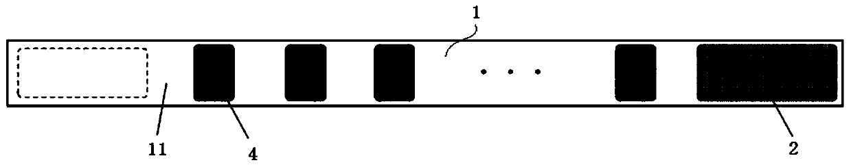
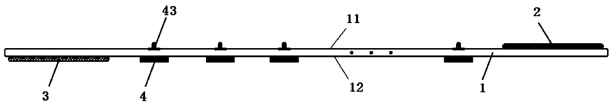
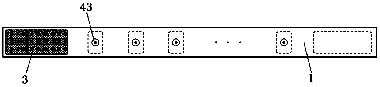
[0057] This embodiment provides an electrode belt, such as Figure 1-3 As shown, it includes: a belt 1, which is elastic, and has a first surface 11 and a second surface 12 opposite to each other; electrodes 4, which have several electrodes, are fixed on the first surface 11, and have the ability to penetrate the belt 1 As for the male buckle 43 exposed on the second surface 12 , the male buckle 43 is electrically connected to the electrode 4 .

[0058] The belt 1 is an elastic fabric, and as a modified design, the belt 1 can be one or a combination of elastic silicone, elastic belts, and rubber belts.

[0059] Along the lengthwise direction of the strip 1 , the electrodes 4 are evenly arranged on the first surface 11 in a row. According to actual needs, the electrodes 4 may also be arranged non-uniformly on the first surface 11 and arranged in at least one row.

[0060] It also includes: a first connection structure 2 arranged on the first surface 11 ; a second connection s...

Embodiment 2

[0065] This embodiment provides an electrode structure that can be applied to the electrode strip described in Embodiment 1, such as Figure 7 As shown, it includes: a flexible printed circuit layer 41; a copper foil layer 42, which has two layers, and is attached to the top surface and the bottom surface of the flexible printed circuit layer 41 to form an inner core layer; a male button 43, and The outermost copper foil layer 42 of the inner core layer is connected in contact; the conductive silica gel 44 covers the inner core layer and exposes the male buckle 43 .

[0066] As a modified design solution, the copper foil layer 42 can also be one layer or more than two layers, which are attached to the top surface and / or bottom surface of the flexible printed circuit layer 41 respectively.

[0067] Specifically, the flexible printed circuit layer 41 and the copper foil layer 42 are bonded together by heat and pressure.

[0068] In the electrode structure of this embodiment, th...

Embodiment 3

[0075] This embodiment provides a feed line, such as Figure 4 , 5 , 6, and 8, including: an electrode feed line 5, one end is suitable for electrical connection with the electrical impedance imaging terminal 6, and the other end is provided with several electrode interfaces 521, and the electrode interface 521 is provided with a female button 50. The female buckle 50 is suitable for buckling with the male buckle 43 described in Embodiment 1 or 2 to realize electrical connection.

[0076] As a preferred solution, the electrode feed line 5 includes: an I-type feed line 51, one end of which is suitable for connecting to the electrical impedance imaging terminal 6, and the other end is extended to branch out into two sub-interfaces 511; a II-type feed line 52 with Two, one end is connected to the sub-interface 511 , and the other end is extended into two sections, each section is provided with four electrode interfaces 521 , and the female buckle 50 is arranged on the electrode ...


PUM


Abstract

The invention provides an electrode band, an electrode structure, a feed line and an electrical impedance imaging device. The electrode band comprises: a band (1) which is elastic and is provided witha first surface (11) and a second surface (12) which are opposite to each other; and a plurality of electrodes (4) fixed on the first surface (11) and provided with male buckles (43) which penetratethrough the belt (1) and are exposed on the second surface (12), wherein the male buckles (43) are electrically connected with the electrodes (4). The electrode band is simple in structure and low incost, and can rapidly and conveniently fix the electrodes to the body of an object to be measured, and the fixing efficiency is high; when the electrode band elastic, so when the electrode band is fixed on the periphery of the thoracic cavity of the measured object, the elastic force of the band is converted into pressing force on the electrodes, so that good contact between the electrodes and theskin of the thoracic cavity can be ensured; and the electrode band and the feed line are arranged in a split mode through the male buckle and the female buckle, so the design of the electrode band issimplified, the feed line can be repeatedly used, and the replacement cost of the electrode band is reduced.

Description

technical field [0001] The invention belongs to the technical field of biomedical electrical impedance imaging, and more specifically relates to an electrode belt, an electrode structure, a feeding line and electrical impedance imaging equipment. Background technique [0002] Electrical impedance tomography (Electrical Impedance Tomography, EIT) is a technology that utilizes the electrical impedance characteristics of the measured organism organs and tissues for imaging. The electrical impedance characteristics of various tissues and organs in the living body (such as the thoracic cavity) are significantly different, and the image reconstructed by the electrical impedance imaging technology has a high contrast. Due to the advantages of high resolution, low cost, portable equipment, no radiation and non-invasiveness, electrical impedance imaging has broad application prospects. [0003] In order to perform biomedical electrical impedance imaging, a certain number of electrod...

Claims


Application Information

Patent Timeline
IPC IPC(8): A61B5/053
CPCA61B5/0536A61B5/251A44B11/25A44D2200/12A61B2562/0209A61B5/6831A61B2562/227
Inventor 林智超张昕于洋
Owner BEIJING HUARUI BOSHI MEDICAL IMAGING TECH CO LTD
Why Eureka
Try Eureka