Solid garbage treatment device for constructional engineering

A technology of solid waste and construction engineering, applied in the field of construction engineering, can solve problems such as waste of iron resources, achieve the effects of saving iron resources, improving grinding efficiency, and being convenient to use

Inactive Publication Date: 2020-04-17
赵文鹏
View PDF1 Cites 1 Cited by
  • Summary
  • Abstract
  • Description
  • Claims
  • Application Information

AI Technical Summary

Problems solved by technology

[0003] The currently published Chinese patent authorization announcement number is CN207951574U, a construction solid waste treatment devic

Method used


Image

  • Solid garbage treatment device for constructional engineering
  • Solid garbage treatment device for constructional engineering
  • Solid garbage treatment device for constructional engineering

Examples


Embodiment 1

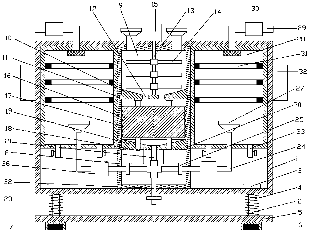
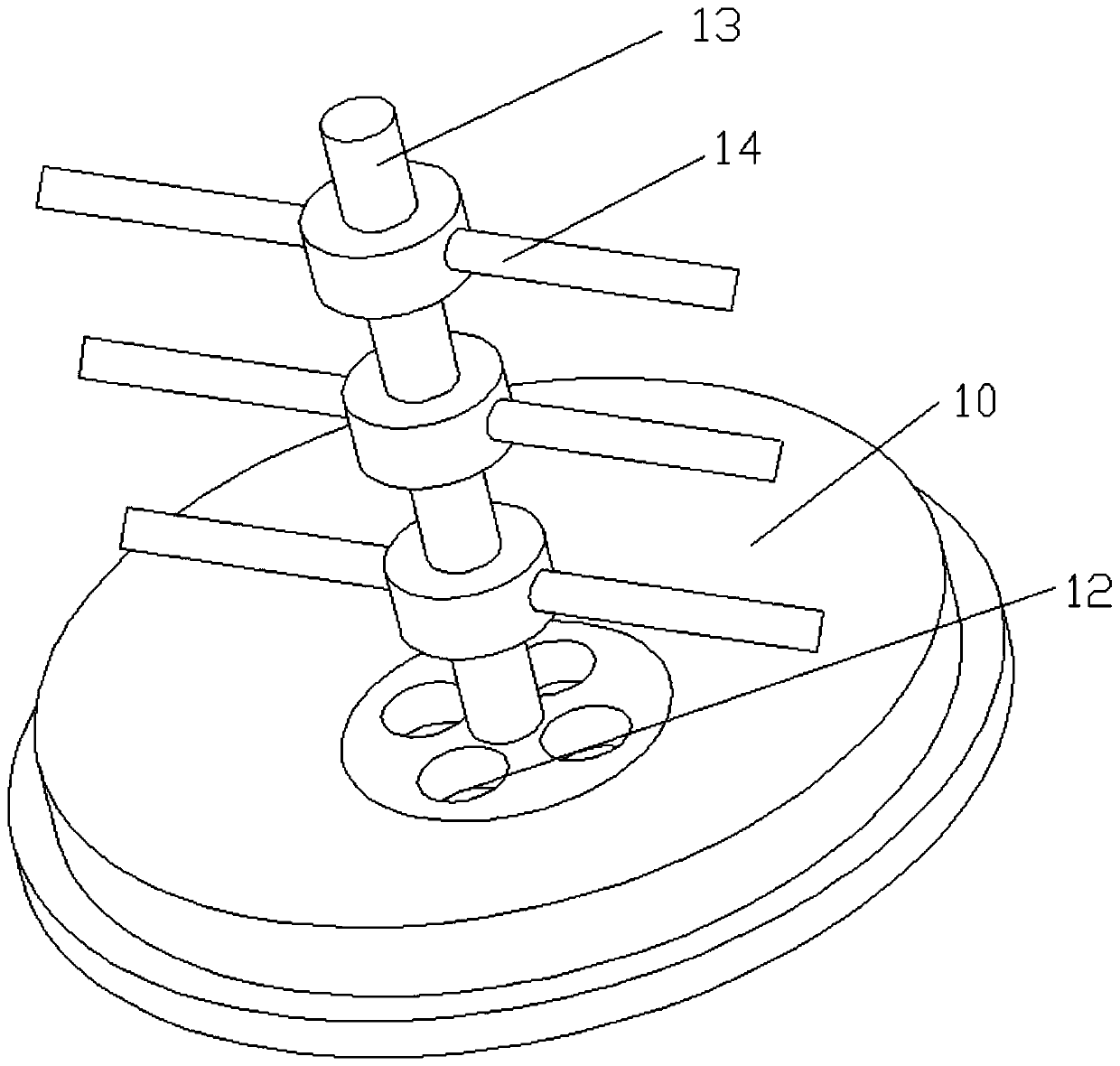
[0025] refer to Figure 1~3 , in an embodiment of the present invention, a solid waste treatment device for construction projects, comprising a support frame 1, a connection chamber 8 is provided in the middle of the support frame 1, a crushing chamber 9 is provided at the upper end of the connection chamber 8, and a crushing chamber 9 is provided at the bottom of the crushing chamber 9 A first rotation guide groove 10 is provided, and the lower end of the first rotation guide groove 10 is inserted into the inside of the first annular limiting groove 11, and the first annular limiting groove 11 is installed on the inner wall of the connecting cavity 8, and the first annular The limit groove 11 can effectively limit the first rotation diversion groove 10, so that the first rotation diversion groove 10 can be rotated smoothly, and the bottom four corners of the first rotation diversion groove 10 are provided with discharge The mouth 12 is convenient for the discharge of the crus...

Embodiment 2

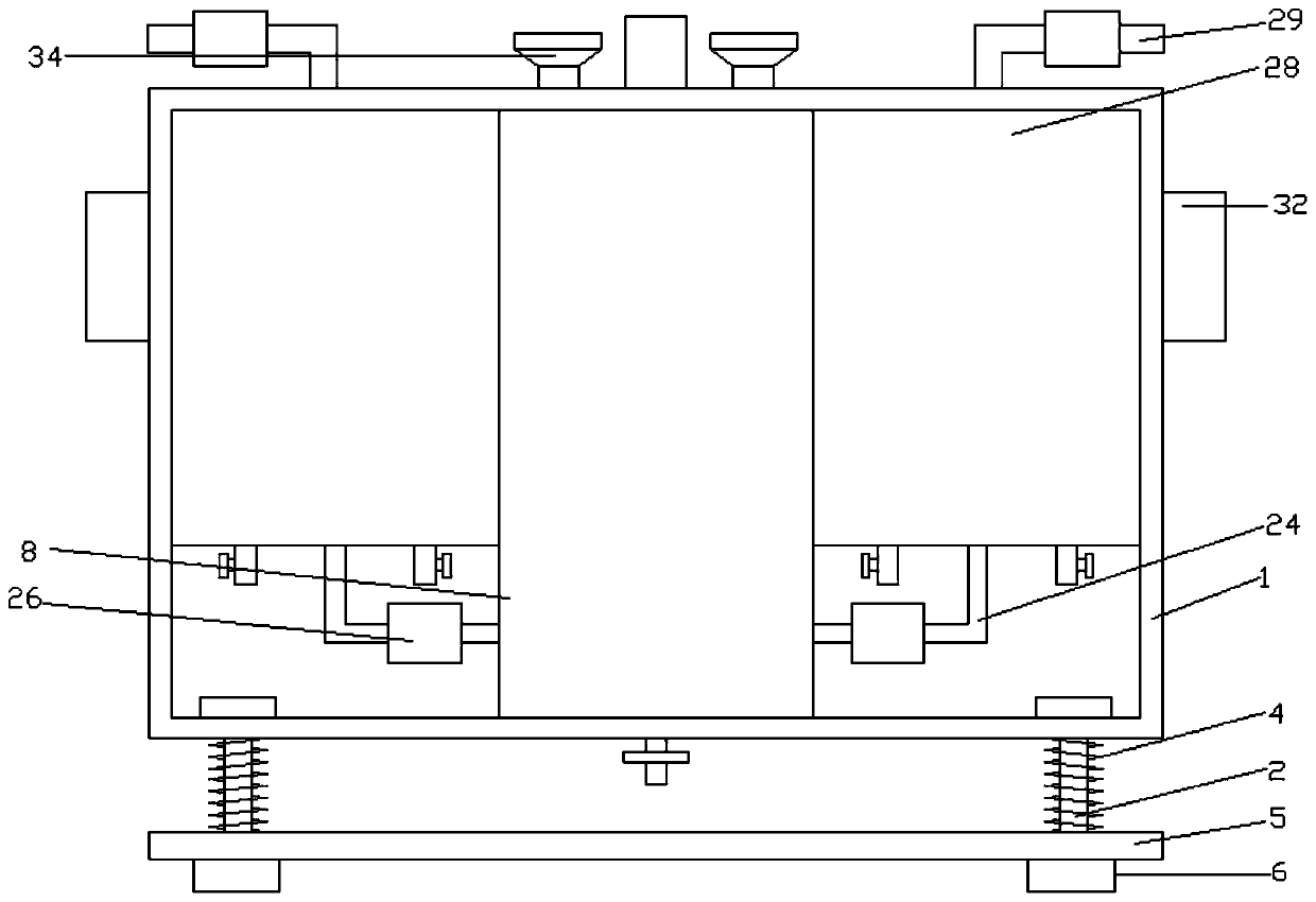
[0030] The difference from Embodiment 1 is that: the four corners of the lower side of the support frame 1 are provided with support columns 2, the upper end of the support column 2 passes through the support frame 1, and the top of the support column 2 is provided with a limit block 3, and the limit block 3 is arranged on the support The bottom of the frame 1 and the lower side of the support column 2 are fixedly equipped with a base plate 5, and a spring 4 is arranged on the support column 2 between the base plate 5 and the support frame 1, which can effectively reduce the vibration of the equipment, so as to ensure the stability of the equipment. The four corners of the lower side of the base plate 5 are fixedly equipped with support blocks 6, and the inner lower end of the support block 6 is inlaid with friction pads 7, which can increase the friction between the support block 6 and the ground, so as to ensure the stability of the equipment.


PUM


Abstract

The invention relates to the field of constructional engineering, in particular to a solid garbage treatment device for constructional engineering. The solid garbage treatment device comprises a supporting framework, wherein a connecting cavity is arranged on the middle part of the supporting framework; a crushing cavity is arranged at the upper end of the connecting cavity; a first rotary guide slot is formed in the bottom of the crushing cavity; discharge holes are formed in the bottom of the first rotary guide slot; a crushing shaft is mounted at the upper side of the first rotary guide slot between the discharge holes; a crushing motor is mounted at the upper side of the crushing shaft; the lower side of the first rotary guide slot is equipped with a grinding roller through a bearing base; the lower side of the grinding roller is equipped with a grinding motor; a discharge tube is arranged on the middle part of the lower side of the second rotary guide slot; left and right ends ofthe discharge tube are connected with a first air exhaust tube through four-way tubes; the other end of the first air exhaust tube is provided with an air-blowing cover; an air exhaust cover is mounted on the bottom of a scrap iron recycling cavity; and a plurality of electromagnet rings are arranged at the upper end of the scrap iron recycling cavity. The solid garbage treatment device can effectively separate scrap iron in solid garbage, so that waste of iron resources is reduced.

Description

technical field [0001] The invention relates to the field of construction engineering, in particular to a solid waste treatment device for construction engineering. Background technique [0002] Construction engineering refers to the engineering entity formed through the construction of various housing buildings and their ancillary facilities and the installation activities of supporting lines, pipelines and equipment. Among them, "house construction" refers to projects that have roofs, beams, walls, foundations, and can form internal spaces to meet people's needs for production, living, learning, and public activities. During the construction process of construction projects, a lot of solid waste is often generated , if not treated in time, it will cause environmental pollution. [0003] The currently published Chinese patent authorization announcement number is CN207951574U, a construction solid waste treatment device. Although it can be crushed, iron filings are often co...

Claims


Application Information

Patent Timeline
IPC IPC(8): B02C18/10B02C4/08B02C23/30B03C1/02
CPCB02C4/08B02C18/0092B02C18/10B02C23/30B02C2201/06B03C1/02
Inventor 赵文鹏
Owner 赵文鹏
Why Eureka
Try Eureka