
A cleaning control system and method thereof

A control system and switching valve technology, applied in the cleaning field, can solve the problems of dead angle, low degree of automation, poor descaling effect, etc., and achieve the effect of improving cleaning efficiency, improving automatic control operation of equipment, and reducing cleaning time

Active Publication Date: 2022-06-24
李锦记(广州)食品有限公司
View PDF12 Cites 0 Cited by
  • Summary
  • Abstract
  • Description
  • Claims
  • Application Information

AI Technical Summary

Problems solved by technology

However, most of the existing CIP cleaning systems are not fully functional, not smart enough, and the degree of automation is not high. There are often dead spots in the cleaning of the reactor, resulting in poor descaling effect.

Method used


Image

  • A cleaning control system and method thereof

Examples


Embodiment Construction

[0026] The technical solutions of the embodiments of the present invention will be described below with reference to the accompanying drawings.

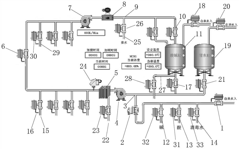
[0027] A cleaning control system includes a first tap water valve 1, a check valve 2, a first three-way pipe 3, a water supply pump 4, a plate heat exchanger 5, and a first on-off valve 6 arranged in sequence according to the direction of liquid flow through water pipes. , return pump 7 , flow meter 8 , second three-way pipe 9 , second switch valve 10 and acid-base cylinder 11 .

[0028] The water pipe between the first tap water valve 1 and the check valve 2 is communicated with an alkali water pipe 12, an acid water pipe 13 and a disinfection water pipe 14. The alkali water pipe 12 is provided with an alkali water valve 32, and the acid water pipe 13 is provided with an acid water valve 31. The disinfection water pipe 14 is provided with a disinfection water valve 33 .

[0029] The water pipe between the plate heat exchanger 5 and...


PUM


Abstract

The invention relates to a cleaning control system and a method thereof, belonging to the technical field of cleaning. It includes five steps of hot water cleaning, alkaline water cleaning, acid water cleaning, clear water cleaning and disinfectant water cleaning. It has the advantages of eliminating frequent contact of personnel with chemicals, stabilizing the control of CIP water concentration, reducing cleaning time, improving cleaning efficiency and improving automatic control operation of equipment.

Description

technical field [0001] The invention relates to the technical field of cleaning, in particular to a cleaning control system and a method thereof. Background technique [0002] In the pharmaceutical, printing and dyeing, and food processing industries, production equipment and pipelines will produce some deposits after use. The deposits remain on the pipeline wall, which is easy to cause pollution or even block the pipeline. It is necessary to regularly clean and maintain the equipment. If the quality of the cleaning work However, the quality of the product will be seriously affected. The conventional cleaning system is offline cleaning. During cleaning, the entire production equipment needs to be shut down first, and then the equipment to be cleaned is disassembled. After disassembly, each part is repeated. Cleaning until it is clean, and finally assembling the cleaned equipment and then resuming production. The whole process is time-consuming, labor-intensive, and labor-int...

Claims


Application Information

Patent Timeline
Patent Type & Authority Patents(China)
IPC IPC(8): B08B9/027B08B9/032
CPCB08B9/027B08B9/032
Inventor 冯志明罗箫程伟燕汤志乾
Owner 李锦记(广州)食品有限公司
Learn More