Device for changing waste roller into shared umbrella placement vehicle and manufacturing method

A manufacturing method and drum technology, applied in the direction of manufacturing tools, other manufacturing equipment/tools, etc., can solve problems such as waste of time, single function of cutting device, low efficiency, etc., to save time, improve maximum utilization, and improve production efficiency effect

Pending Publication Date: 2020-04-17
AOSHIKANG TECH CO LTD
View PDF0 Cites 3 Cited by
  • Summary
  • Abstract
  • Description
  • Claims
  • Application Information

AI Technical Summary

Problems solved by technology

[0003] At present, when refitting waste drums, a cutting device is generally required. The traditional cutting device has a single function, and one operation of the device can only cut the drum once. Cutting, the efficiency is low, and after the drum is cut, it is necessary to polish and polish the cut drum with a grinding device. It also increases the working hours and increases the production cost

Method used


Image

  • Device for changing waste roller into shared umbrella placement vehicle and manufacturing method
  • Device for changing waste roller into shared umbrella placement vehicle and manufacturing method
  • Device for changing waste roller into shared umbrella placement vehicle and manufacturing method

Examples


Embodiment 1

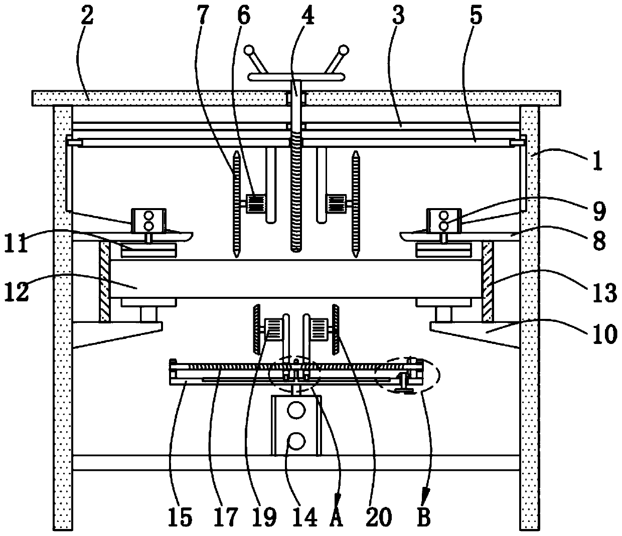
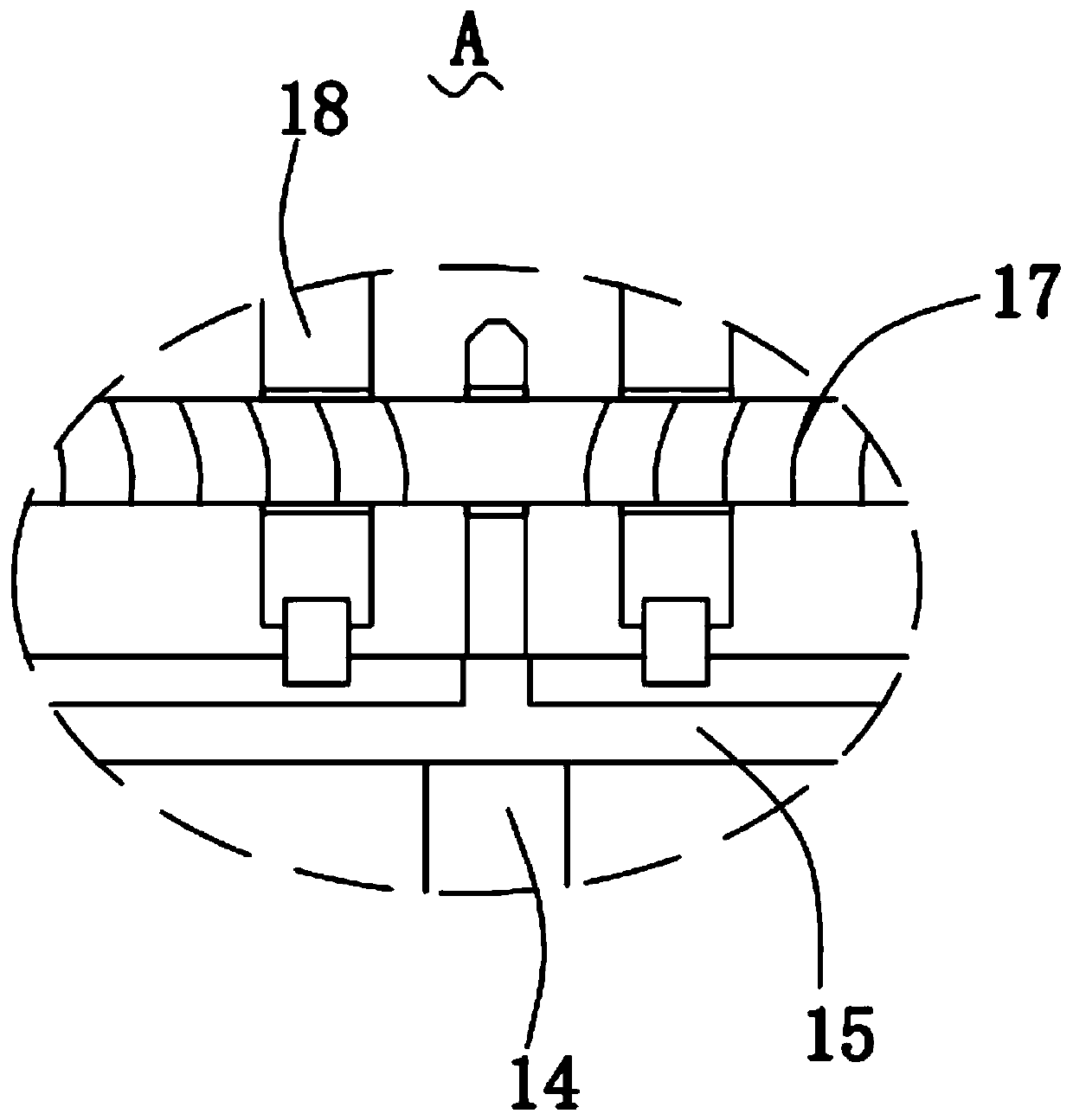
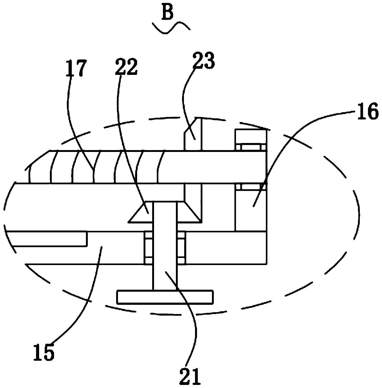
[0028] Please refer to Figure 1-Figure 4 ,in figure 1 It is a structural schematic diagram of a preferred embodiment of a device for refitting a shared umbrella with a discarded roller proposed by the present invention; figure 2 for figure 1 The enlarged schematic diagram of part A shown; image 3 for figure 1 The enlarged schematic diagram of part B shown; Figure 4 for figure 1 Schematic diagram of the side view structure of the curved splint shown.

[0029] In this embodiment, a device for refitting a shared umbrella with discarded rollers is proposed, including two side fixing plates 1; a cover plate 2, and the cover plate 2 is fixedly installed on the top of the two side fixing plates 1; a reinforcing plate 3. The reinforcing plate 3 is fixedly installed on the side where the two side fixing plates 1 are close to each other; the first screw 4, the first screw 4 is rotatably installed on the cover plate 2 and the reinforcing plate 3 On the movable plate 5, the mov...

Embodiment 2

[0039] In this embodiment, a method for making a vehicle for refitting a shared umbrella with discarded rollers is proposed, including the following steps:

[0040] S1: Material selection: Select a suitable waste roller, two sealing plates that match the diameter of the roller, two iron sheets for umbrella storage, three connecting rods, a load-bearing base and four universal wheels.

[0041] S2: Cutting into sections: Cut the selected waste drum into two sections of the same size, and then polish the cut surface.

[0042] S3: Material welding: Weld two sealing plates on one side of the two-section drum respectively to seal the opening on one side, and then weld the two umbrella storage iron plates on the other opening side of the two-section drum respectively, and then The three connecting rods are welded on the top of the load-bearing base, and the two rollers are welded to the three connecting rods. The distance between the two rollers can be adjusted according to the lengt...


PUM


Abstract

The invention provides a device for changing a waste roller into a shared umbrella placement vehicle and a manufacturing method. The device for changing the waste roller into the shared umbrella placement vehicle comprises two side edge fixing plates, a cover plate fixedly mounted at the tops of the two side edge fixing plates, a reinforcing plate fixedly mounted on the sides, close to each other,of the two side edge fixing plates, a first screw rod rotationally mounted on the cover plate and the reinforcing plate and a movable plate installed on the first screw rod in a threaded mode, and the two sides of the movable plate are connected with the sides, close to each other, of the two side edge fixing plates in a sliding mode correspondingly. The device for changing the waste roller intothe shared umbrella placement vehicle and the manufacturing method have the advantages that time is saved, production efficiency is improved, production cost is reduced, and waste can be recycled.

Description

technical field [0001] The invention relates to the technical field of recycling, in particular to a device and a manufacturing method for refitting a discarded roller into a vehicle for placing a shared umbrella. Background technique [0002] Recycling refers to the recycling of useful substances separated from waste through physical or mechanical processing, such as waste glass, waste metal, waste batteries, old home appliances, idle gifts, etc. With the continuous promotion of the sharing economy , more and more shared resources appear in modern society, such as shared umbrella storage vehicles, shared bicycles and shared charging treasures. In the case of profit, use the discarded drum to carry out corresponding modification. This method can not only recycle the waste, but also bring corresponding economic benefits to the enterprise, so it can be widely promoted. [0003] At present, when refitting waste drums, a cutting device is generally required. The traditional cut...

Claims


Application Information

Patent Timeline
Patent Type & Authority Applications(China)
IPC IPC(8): B23P23/04
CPCB23P23/04
Inventor 张震杨先卫李晓维
Owner AOSHIKANG TECH CO LTD
Why Eureka
Try Eureka