Inlay composite flat plate die-cutting machine

A technology of die-cutting machine and flat plate, which is applied in the field of Inlay compounding, can solve the problems of high cost, high cost of die-cutting tools, and poor versatility, and achieve the effects of stable rotation, strong versatility, and avoiding jamming

Pending Publication Date: 2020-04-17
南通海元芯盛智能科技有限公司
View PDF1 Cites 5 Cited by
  • Summary
  • Abstract
  • Description
  • Claims
  • Application Information

AI Technical Summary

Problems solved by technology

[0004] The above-mentioned inlay electronic label production device still has certain defects in the production process: when the inlay is die-cut, it is realized by the cooperation of rotary knives, flat knives, vacuum drums and other components. When the rotary knife rotates, it cooperates with the flat knife to realize the equidistant cutting of the inlay. The structure of the existing rotary knife is usually to attach a layer of die-cutting tool on the circumferential surface of the circular shaft, and then realize the inlay cutting through the rotation of the circular shaft. The equidistant cutting of the label, and such a cutting method, the cutting distance of the Inlay label is affected by the size of the die-cutting tool, that is, a die-cutting tool of one size can only achieve the cutting of an Inlay label of one specification Yes, when it is necessary to cut Inlay labels of different specifications, it is necessary to attach die-cutting knives of different sizes on the round shaft to cooperate. Its versatility is not strong, and the cost of this kind of die-cutting knives is relatively high, so When there are many specifications of Inlay labels to be produced, die-cutting tools of various specifications are required, and the cost is relatively high

Method used


Image

  • Inlay composite flat plate die-cutting machine
  • Inlay composite flat plate die-cutting machine
  • Inlay composite flat plate die-cutting machine

Examples


Embodiment Construction

[0054] The following examples can enable those skilled in the art to understand the present invention more comprehensively, but the present invention is not limited to the scope of the described examples.

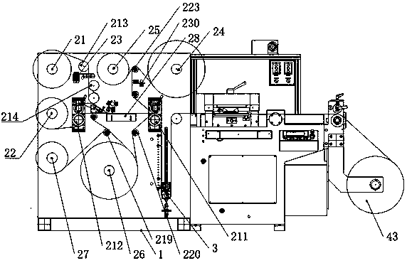
[0055] Such as Figure 1-Figure 5 An Inlay composite flat die-cutting machine shown, including

[0056] A pair of Inlay label composite units and flat die-cutting units arranged side by side, and a buffer unit is arranged between the Inlay label composite unit and the flat die-cut unit.

[0057] The Inlay label composite unit includes a composite frame 1, on which are installed an Inlay unwinding assembly, a substrate unwinding assembly, and a composite traction assembly. The Inlay unwinding assembly includes an Inlay unwinding roller 21 and an Inlay waste collection roller 22. , the Inlay unwinding roller 21 and the Inlay waste collecting roller 22 are distributed side by side on the compound frame 1 up and down.

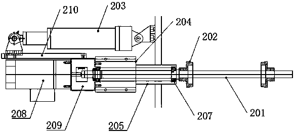
[0058] Such as figure 2 As can be seen from the schema...


PUM


Abstract

The invention relates to an Inlay composite flat plate die-cutting machine, which comprises a pair of Inlay label composite units distributed in parallel and a flat plate die-cutting unit. A buffer unit is further arranged between the Inlay label composite units and the flat plate die-cutting unit. The Inlay label composite unit comprises a composite rack. An Inlay unwinding assembly, a base material unwinding assembly and a composite traction assembly are installed on the composite rack, and the Inlay unwinding assembly comprises an Inlay unwinding roller and an Inlay waste collecting roller.The flat plate die-cutting unit comprises a pair of cutting die upper plates which are distributed up and down, a cutting die bottom plate and a finished product winding roller. The Inlay composite flat plate die-cutting machine has the advantages that the Inlay label composite unit, the flat plate die-cutting unit and the buffer unit are matched with one another, accordingly, flat plate die-cutting can be carried out on composite material strips, and the machine can be suitable for cutting various Inlay composite material strips of different specifications without replacing tools of different sizes by the aid of the cutting mode.

Description

technical field [0001] The invention relates to the field of Inlay compounding, in particular to an Inlay compounding flat die-cutting machine. Background technique [0002] Inlay is a special term in the smart card industry, which refers to a pre-laminated product composed of multi-layer PVC sheets containing chips and coils. Generally consists of two or three layers. There is no printed pattern on the surface, INLAY products are suitable for the pre-mass production of various cards. INLAY is covered with materials with different printed patterns on the top and bottom, and then laminated again to form a variety of non-contact cards. [0003] At present, in the process of Inlay processing, the Inlay label is combined with the surface material and the substrate. For example, in the patent CN106599978A, a production device for an inlay electronic label is mentioned, including a touch switch, an inlay Coil feed roller, guider, self-adhesive label feed roller, auxiliary mater...

Claims


Application Information

Patent Timeline
Patent Type & Authority Applications(China)
IPC IPC(8): B26F1/44B26F1/38B65H23/26
CPCB26F1/38B26F1/44B65H23/26
Inventor 许哲
Owner 南通海元芯盛智能科技有限公司
Why Eureka
Try Eureka