Electromagnetic overhead crane with rail cleaning function

A bridge crane and cleaning technology, which is applied to cleaning methods and tools, cleaning methods using tools, mechanical equipment, etc., can solve problems such as incomplete cleaning, vibration of bridge operating mechanism, and reduced cleaning efficiency of tracks to achieve good cleaning effect , Improve the effect of cleaning efficiency

Inactive Publication Date: 2020-04-17
东阳格盘机械科技有限公司
View PDF5 Cites 6 Cited by
  • Summary
  • Abstract
  • Description
  • Claims
  • Application Information

AI Technical Summary

Problems solved by technology

Since the crane slides on the track for a long time, hard objects will accumulate on the track, such as iron blocks, sand and gravel, etc. When the dust and rust attached to the track pass through the bridge sliding mechanism of the bridge crane and the walking and After rolling, a thin layer of skin will be formed between the wheel and the track of the bridge crane. Long-term accumulation will prevent the vehicle from directly contacting the track, and the track will be easily worn. When there are too many debris accumulated on the track, it will cause the vibration of the bridge operating mechanism. , affecting the stability of the overall structure of the crane, therefore, it is necessary to clean up the dust, rust and other sundries attached to the track in time
At present, the cleaning method of the bridge crane track is mainly completed by the rail sweeping plate. The rail sweeping plate intelligently cleans the hard objects on the track, and cannot clean the dust, rust and other fine particles attached to the track. Reduced cleaning efficiency

Method used


Image

  • Electromagnetic overhead crane with rail cleaning function
  • Electromagnetic overhead crane with rail cleaning function
  • Electromagnetic overhead crane with rail cleaning function

Examples


Embodiment Construction

[0018] All features disclosed in this specification, or steps in all methods or processes disclosed, may be combined in any manner, except for mutually exclusive features and / or steps.

[0019] Combine below Figure 1-5 The present invention is described in detail, and for convenience of description, the orientations mentioned below are now stipulated as follows: figure 1 The up, down, left, right, front and back directions of the projection relationship itself are the same.

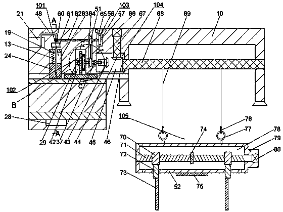
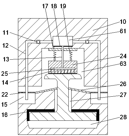
[0020] An electromagnetic bridge crane with a track cleaning function of the device of the present invention includes a base body 10 and a lifting block 79, the base body 10 is provided with a working chamber 63, and the working chamber 63 is provided with a chip removal mechanism 101, A cleaning chamber 27 is provided below the working chamber 63, a cleaning chamber 42 is provided on the right side of the working chamber 63, a cleaning mechanism 102 is provided in the cleaning chamber 42, and a first r...


PUM


Abstract

The invention discloses an electromagnetic overhead crane with a rail cleaning function. The electromagnetic overhead crane comprises a base body and a lifting block. A working cavity is formed in thebase body and internally provided with a debris removal mechanism. A cleaning cavity is arranged below the working cavity. A sweeping cavity is arranged on the right side of the working cavity. A sweeping mechanism is arranged in the sweeping cavity. A first rectangular groove is formed in the right side of the sweeping cavity. A first rotating shaft is rotationally arranged between the first rectangular groove and the sweeping cavity. The left end of the first rotating shaft extends into the sweeping cavity and is fixedly provided with a first chain wheel. The right end of the first rotatingshaft extends into the base body and is fixedly provided with an electric push rod. A first belt wheel fixedly connected with the first rotating shaft is arranged in the first rectangular groove. A transmission cavity is formed in the right side of the first rectangular groove. A transmission mechanism is arranged in the transmission cavity. A second rotating shaft is rotationally arranged between the transmission cavity and the first rectangular groove.

Description

technical field [0001] The invention relates to the technical field of cranes, in particular to an electromagnetic bridge crane with track cleaning function. Background technique [0002] Electromagnetic bridge crane is a device that uses electromagnets to carry steel materials, called electromagnetic cranes. Since the crane slides on the track for a long time, hard objects will accumulate on the track, such as iron blocks, sand and gravel, etc. When the dust and rust attached to the track pass through the bridge sliding mechanism of the bridge crane and the walking and After rolling, a thin layer of skin will be formed between the wheel and the track of the bridge crane. Long-term accumulation will prevent the vehicle from directly contacting the track, and the track will be easily worn. When there are too many debris accumulated on the track, it will cause the vibration of the bridge operating mechanism. , affecting the stability of the overall structure of the crane, the...

Claims


Application Information

Patent Timeline
Patent Type & Authority Applications(China)
IPC IPC(8): B66C13/00F16N39/04F16F15/04B08B1/00
CPCB08B1/00B66C13/00F16F15/04F16N39/04
Inventor 不公告发明人
Owner 东阳格盘机械科技有限公司
Why Eureka
Try Eureka