Printing and eyeing machine capable of filtering printing and dyeing sewage

A technology for printing and dyeing sewage and printing and dyeing machines, which is applied in the field of printing and dyeing, can solve problems such as damage to conveying equipment, discharge, and external environmental pollution, and achieve the effect of improving the efficiency of printing and dyeing work and increasing the flow of filtration.

Inactive Publication Date: 2020-04-17
HANGZHOU JIANYI TECHNOLOGY CO LTD
View PDF9 Cites 0 Cited by
  • Summary
  • Abstract
  • Description
  • Claims
  • Application Information

AI Technical Summary

Problems solved by technology

[0004] The purpose of the present invention is to provide a printing and dyeing machine that can filter printing and dyeing sewage, so as to solve the problem that the existing printing and dyeing machine proposed in the above background technology generally transports clothing fabrics through transmission equipment during use, so that it needs to be started and stopped at any time The transmission equipment is easy to cause damage to the transmission equipment, and the sewage after the printing and dyeing work is directly discharged to the outside, causing the pollution of the external environment

Method used


Image

  • Printing and eyeing machine capable of filtering printing and dyeing sewage
  • Printing and eyeing machine capable of filtering printing and dyeing sewage
  • Printing and eyeing machine capable of filtering printing and dyeing sewage

Examples


Embodiment Construction

[0026] The technical solutions in the embodiments of the present invention will be clearly and completely described below in conjunction with the accompanying drawings in the embodiments of the present invention. Obviously, the described embodiments are only a part of the embodiments of the present invention, rather than all the embodiments. Based on the embodiments of the present invention, all other embodiments obtained by those of ordinary skill in the art without creative work shall fall within the protection scope of the present invention.

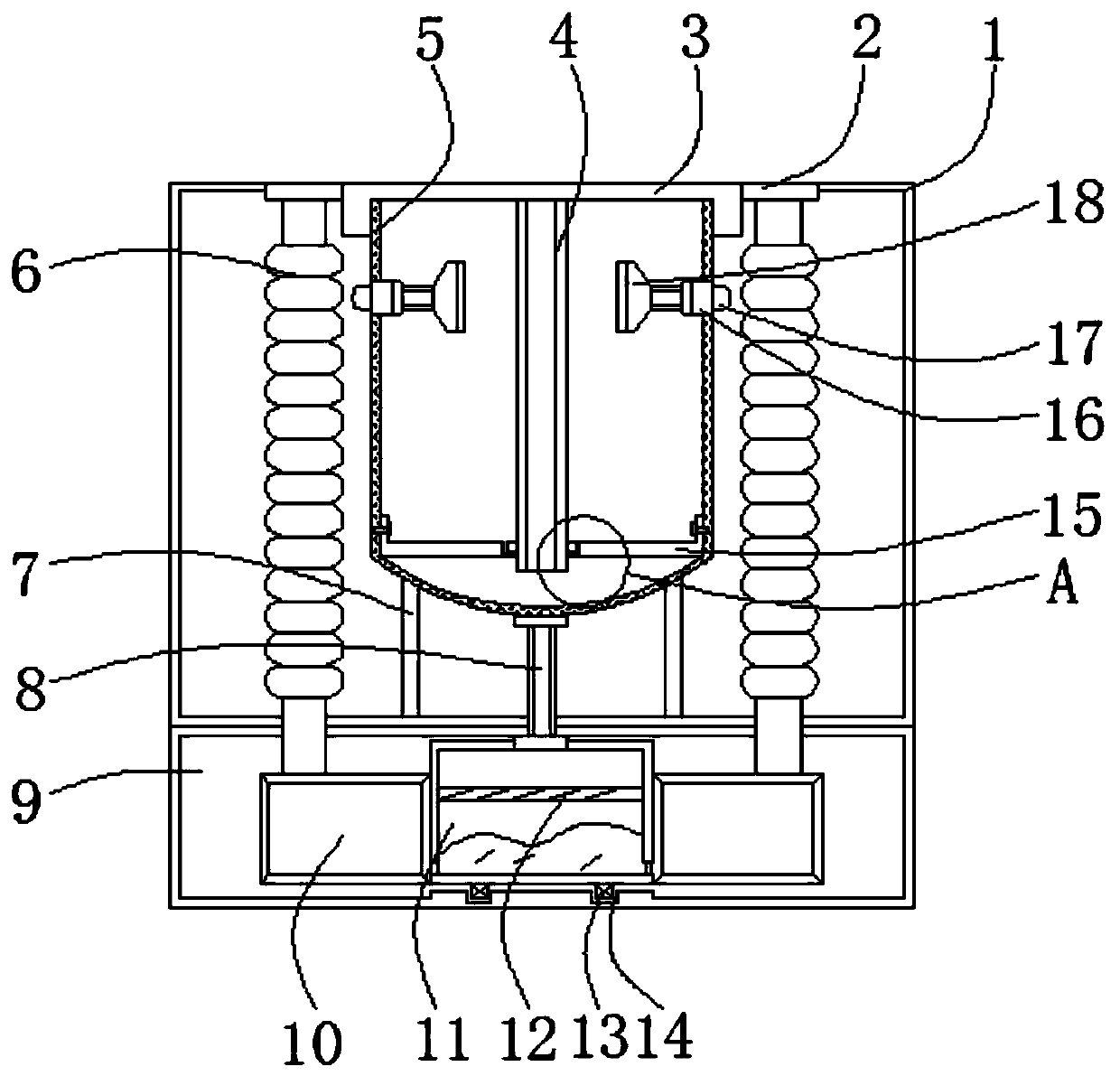
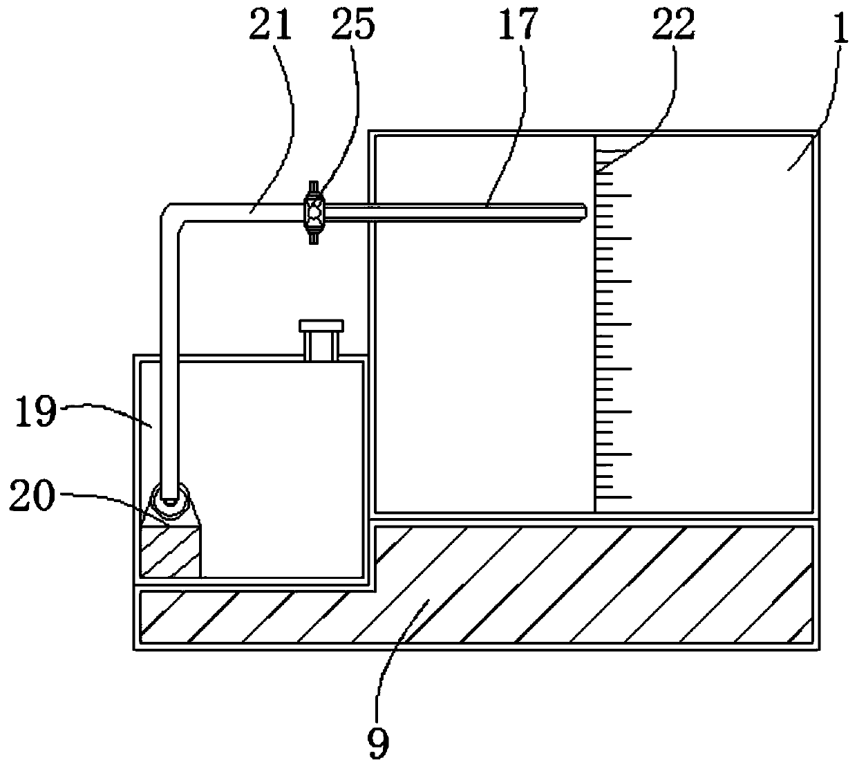
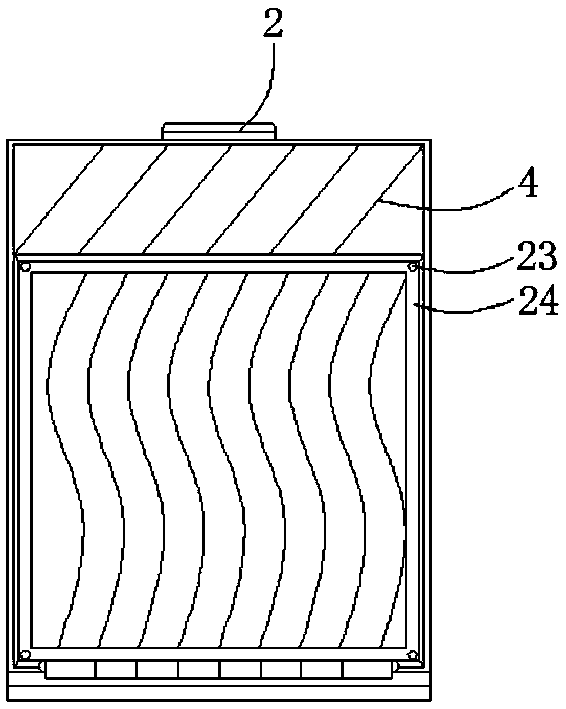
[0027] See Figure 1-5 , The present invention provides a technical solution: a printing and dyeing wastewater filterable printing and dyeing machine, comprising a main body 1, a movable plate 2, a movable cover 3, a movable frame 4, a printing and dyeing bin 5, a trachea 6, a supporting block 7, a connecting pipe 8, Support base 9, communication box 10, storage tank 11, filter screen 12, slider 13, chute 14, support plate 15, telescopic...


PUM


Abstract

The invention relates to a printing and dyeing machine capable of filtering printing and dyeing sewage. The printing and dyeing machine comprises a main body, a supporting seat and a telescopic rod, wherein a movable cover is mounted on the top of the main body and is in threaded connection with the main body; a movable plate is movably arranged in the middle of the top of the movable cover; a movable frame is connected to the bottom of the movable plate; and the movable frame is fixedly connected with the movable plate. The printing and dyeing machine has the beneficial effects that a communicating box, a storage tank, an air pipe, a filter screen and the main body are arranged, the communicating box and the storage tank are of a communicating structure, and when the inner side of a printing and dyeing bin conducts printing and dyeing work on garment fabric, generated printing and dyeing sewage flows into the storage tank along a connecting pipe in the middle of the bottom of the printing and dyeing bin, under the action of the communicating box forming the communicating structure with the storage groove, the printing and dyeing sewage flows into the communicating box, the gas pressure intensity between the printing and dyeing sewage and the inner sides of branch pipes is increased, the branch pipes made of elastic materials rise upwards, and the movable plate and the movableframe are lifted.

Description

Technical field [0001] The invention relates to the technical field of printing and dyeing, in particular to a printing and dyeing machine capable of filtering printing and dyeing sewage. Background technique [0002] With the development of science and technology and the progress of the social era, printing and dyeing technology is becoming more and more excellent, and printing and dyeing is also called dyeing and finishing, which is a processing method. At present, in the production of clothing fabrics, it is often necessary to print and dye clothing fabrics. When the dye is stored and precipitated in the dye tank for a long time, the density of the dye is uneven. If the dye is printed directly, it is easy to cause problems such as color difference in printing and dyeing, and unstable color in some positions, which affects the quality of the fabric. [0003] In the process of using the existing printing and dyeing machine, the clothing fabric is generally conveyed through the con...

Claims


Application Information

Patent Timeline
Patent Type & Authority Applications(China)
IPC IPC(8): D06B1/02D06B23/04D06B23/20
CPCD06B1/02D06B23/20D06B23/04
Inventor 余成鹏
Owner HANGZHOU JIANYI TECHNOLOGY CO LTD
Why Eureka
Try Eureka