
Cement laying device for building engineering

A technology of construction engineering and laying device, applied in construction, building structure, processing of building materials, etc., can solve the problems of engineering quality, hollow, unable to lay cement, etc., and achieve the effect of easy pressing and increasing pressing area.

Inactive Publication Date: 2020-04-17
深圳市河图建设项目管理有限公司
View PDF1 Cites 5 Cited by
  • Summary
  • Abstract
  • Description
  • Claims
  • Application Information

AI Technical Summary

Problems solved by technology

[0005] Based on the fact that the general bricklaying robot cannot pave the cement well when it is in use, which may cause a hollow inside after the cement is laid, resulting in technical problems of engineering quality, the present invention proposes a cement laying device for construction engineering

Method used


Image

  • Cement laying device for building engineering
  • Cement laying device for building engineering
  • Cement laying device for building engineering

Examples


Embodiment 1

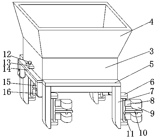
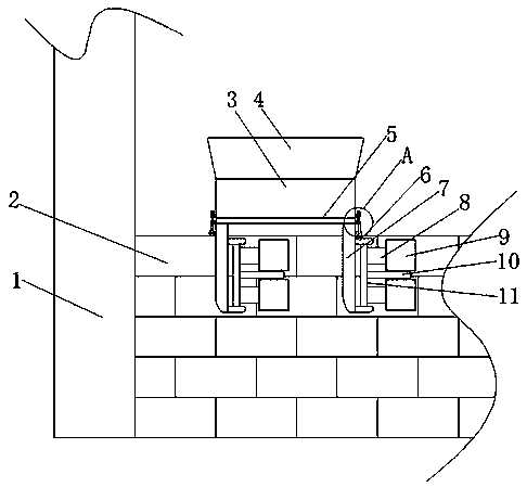
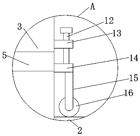
[0030] refer to Figure 1-5 , a cement laying device for construction engineering, comprising a column 1 and a main body 3 at the top of the wall 2, the middle part of the main body 3 is welded with a third fixed plate 24, and the bottom end of the third fixed plate 24 is welded with a pressing plate 25, the first The top of three fixed plate 24 is welded with spring 20, and the top of spring 20 is welded with rotating plate 18, and one end of rotating plate 18 is connected with main body 3 rotations, and the internal rotation of main body 3 is connected with rotating body 17, and the exterior of rotating body 17 is welded with A plurality of pressing blocks 26, the rotating body 17 is on one side of the third fixed plate 24, the first fixed plate 5 is welded on both sides of the main body 3, and the bottom end of the first fixed plate 5 is welded with two first fixed columns 7 , one side of the first fixed column 7 is welded with two fixed blocks 6, and a rotating rod 11 is c...

Embodiment 2

[0040] refer to Image 6 , a cement laying device for construction engineering. Compared with Embodiment 1, in this embodiment, in order to enhance the practicability of the device, facilitate the movement of the device and the adhesion between cement and bricks, one side of the main body 3 is welded with a handle 27 , the bottom end of the handle 27 is welded with a connecting rod 28, the bottom end of the connecting rod 28 is welded with a fourth fixed plate 29, the fourth fixed plate 29 is V-shaped, and the bottom end of the fourth fixed plate 29 is provided with a brush 30, through During the process of pulling the main body 3 by the handle 27, the V-shaped brush 30 can push the dust on the brick surface to both sides, so as to increase the adhesion between the cement and the brick.

[0041] When in use, the device can walk on the wall 2 through the second rollers 23. While walking, the two layers of second rollers 23 contact and clamp the two layers of bricks respectively...


PUM


Abstract

The invention belongs to the technical field of engineering buildings, and particularly relates to a cement laying device for building engineering. Aiming at the problem that a general bricklaying robot cannot well lay cement during use, so that hollow possibly exists inside the cement after the cement is laid, and engineering quality problems are caused, the following scheme is presented now. According to the scheme, the cement laying device comprises a stand column and a main body located at the top end of a wall body, wherein a third fixing plate is welded to the middle of the main body, apressing plate is welded to the bottom end of the third fixing plate, a spring is welded to the top end of the third fixing plate, and a rotating plate is welded to the top end of the spring. According to the cement laying device, the device encounters a gap between bricks in the travelling process to form jounce and up-down shaking, the rotating plate is formed to rotate up and down through the spring, the inclined rotating plate enables the cement to quickly slide on the wall body, the cement can drive a rotating body to rotate through pressing blocks in the sliding process, and the pressingblocks press the cement falling on the wall body in the rotating process, so that air in the cement is discharged.

Description

technical field [0001] The invention relates to the technical field of engineering construction, in particular to a cement laying device for construction engineering. Background technique [0002] Bricklaying is an important part of construction projects. When laying bricks, cement needs to be laid on the surface of the brick body first. However, in construction projects, manual bricklaying is used when laying bricks. The efficiency is slow, and the quality cannot be guaranteed. There will be a hollow inside after the cement is laid, causing quality problems in the project. [0003] After retrieval, the Chinese Patent Publication No. is CN107447996B, which discloses a building cement wall-building device, including a fuselage, a bracket, and a leveling wheel. The upper end of the fuselage is provided with a feed port, and the lower end of the fuselage is provided with a There is a discharge port, one side of the fuselage is open, and a bracket is fixedly installed at the op...

Claims


Application Information

Patent Timeline
Patent Type & Authority Applications(China)
IPC IPC(8): E04G21/20
CPCE04G21/204
Inventor 李超柳晓云柳泽滨陈俊君刘钦杰
Owner 深圳市河图建设项目管理有限公司
Learn More