Friction energy dissipation sleeve reinforcing device and use method thereof

A reinforcement device and frictional energy consumption technology, which is applied in building maintenance, building components, building types, etc., to achieve the effect of improving bearing capacity, simple and effective reinforcement method, and flexible reinforcement operation

Active Publication Date: 2020-04-17
SOUTHEAST UNIV
View PDF6 Cites 0 Cited by
  • Summary
  • Abstract
  • Description
  • Claims
  • Application Information

AI Technical Summary

Problems solved by technology

[0006] The patent with the application number 201510423508.7 discloses a method for strengthening the key members of the comparative space structure. The square constraining parts are composed of steel plates and section steels through bolts. The buckling of the key members is restrained to increase the bearing capacity of the members, but it only improves the strength of the rods. Therefore, how to combine the reinforcement of compression bars to not only increase the strength but also provide additional damping for the structure is an urgent problem to be solved in the reinforcement of compression bars in space structures.

Method used


Image

  • Friction energy dissipation sleeve reinforcing device and use method thereof
  • Friction energy dissipation sleeve reinforcing device and use method thereof
  • Friction energy dissipation sleeve reinforcing device and use method thereof

Examples


Embodiment 1

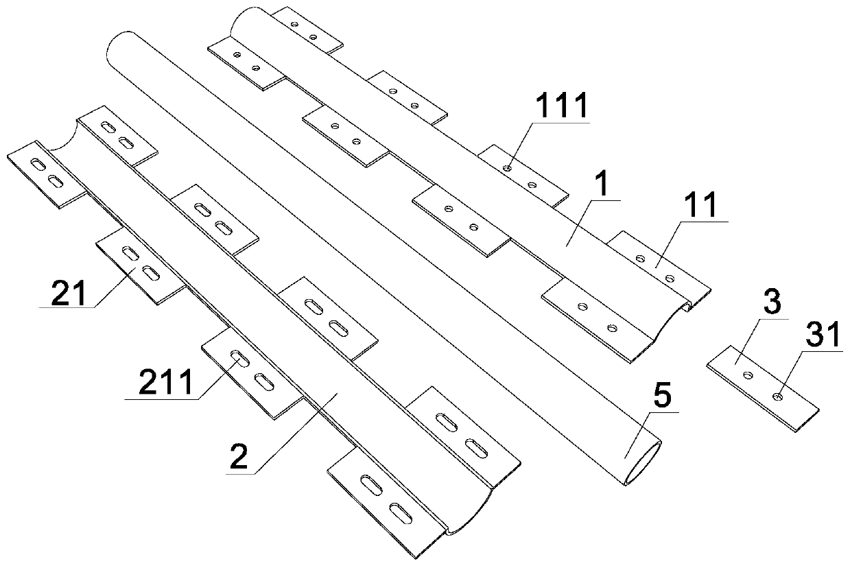
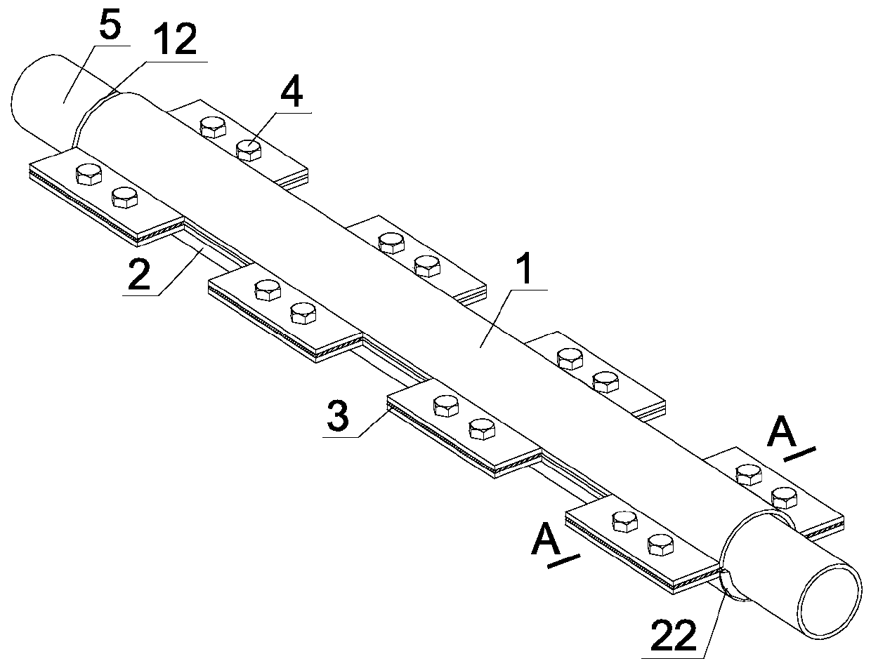
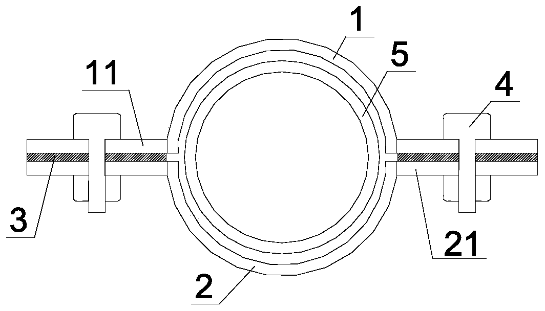
[0030] like Figure 1~3 , use the symmetrical first segment 1 and the second segment 2 to reinforce the pressure bar 5, the first segment 1 includes the first stiffening plate 11 which is evenly distributed along the length direction of the tube and fixedly connected, the first stiffening plate 11 has a circle Hole one 111, the second segment 2 includes second stiffening plates 21 uniformly distributed and fixedly connected along the length of the tube, and the second stiffening plate 21 has a slot one 211 along the length of the tube. The friction sheet 3 is clamped between the first stiffening plate 11 and the second stiffening plate 21. The size of the friction sheet 3 is not larger than the first stiffening plate 11. The friction sheet 3 is a copper sheet and has the same position and size as the round hole 111. Two circular holes 31 are arranged. Round hole 1 111, round hole 2 31 and slot hole 1 211 are fixed by bolts 4 to form the restraint part of the reinforcement bar...

Embodiment 2

[0032] like Figure 4 , This embodiment is the same as the rest of Embodiment 1, except that the first segment 1 and the second segment 2 of polygonal flaps are used, and the friction sheet 3 is non-asbestos organic matter.

Embodiment 3

[0034] like Figure 5 , This embodiment is the same as the rest of Embodiment 1, except that the reinforcement object is a compression bar 5 with an H-shaped steel section.


PUM


Abstract

The invention discloses a friction energy dissipation sleeve reinforcing device and a use method thereof. The device comprises a first pipe piece and a second pipe piece. The first pipe piece comprises a first stiffening plate in the pipe length direction; the second pipe piece comprises second stiffening plates which are uniformly distributed in the length direction of the pipe and are fixedly connected; a friction piecet is arranged between the first stiffening plate and the second stiffening plates, and a first round hole, a second round hole and a first slotted hole are fixed. The method comprises the following steps that the first pipe piece and the second pipe piece with the length less than that of a pressing rod are selected; the first pipe piece and the second pipe piece are oppositely arranged, the first stiffening plate and the second stiffening plates are opposite, the first round hole and the first slotted hole are opposite, and the friction piece is clamped between the first stiffening plate and the second stiffening plates; fixing is performed through bolts; one end of the pressing rod is connected with the end of the first pipe piece through a first weld joint, andthe other end is connected with the end of the second piece piece through a second weld joint. Restraint is provided for buckling of the pressing rod, a friction type damper is formed and thus the bearing capacity of the pressing rod and the energy dissipation capacity of the structure can be improved.

Description

technical field [0001] The invention relates to compression rod reinforcement, in particular to a frictional energy dissipation sleeve reinforcement device and a method for using the same. Background technique [0002] With the development of science and technology and the improvement of people's living standards, more and more attention has been paid to the large-span spatial structure. The spatial structure has the characteristics of beautiful shape, reasonable economy, and large span. It is widely used in stadiums, terminal buildings, exhibitions, etc. Important public buildings with large or even super-large spaces, such as centers, fully demonstrate the latest achievements in structural technology and the charm of structural modeling, and have huge social influence. [0003] The stability of the key compression members in the space structure has a great influence on the bearing capacity of the entire structure. The overload of the key compression members will be the fir...

Claims


Application Information

Patent Timeline
Patent Type & Authority Applications(China)
IPC IPC(8): E04G23/02E04H9/02E04B1/98
CPCE04G23/0218E04H9/021E04B1/98
Inventor 曾滨王春林袁玥卿缘
Owner SOUTHEAST UNIV
Why Eureka
Try Eureka