
Method for improving power generation efficiency of water turbine and inhibiting cavitation erosion of spare parts of water turbine

A technology of power generation efficiency and water turbines, applied in the fields of hydropower generation, machines/engines, engine components, etc., can solve the problems of complex design, erosion of water turbines, high prices, etc., and achieve the effect of suppressing cavitation, preventing cavitation, and increasing pressure.

Active Publication Date: 2020-04-17
林瑞麟
View PDF7 Cites 0 Cited by
  • Summary
  • Abstract
  • Description
  • Claims
  • Application Information

AI Technical Summary

Problems solved by technology

[0005] However, there is a special physical phenomenon in the operation of the turbine, that is, the impact of high-speed water on the guide plate, impeller and other related parts and accessories of the turbine produces high-pressure areas and low-pressure areas. In the high-pressure area, the potential energy and kinetic energy of the water are converted into electrical energy. In the low-pressure area, when part of it is lower than the vapor pressure of water, the water vaporizes to generate cavitation, which leads to erosion of the components of the turbine, thus affecting the efficiency and service life of the turbine
However, in order to prevent the cavitation of the relevant parts and accessories of the water turbine, only cavitation-resistant special metal materials can be used, but the price is high and difficult to process, such as ASTM A487 stainless steel and other special stainless steel materials
[0006] However, in order to improve the above problems, overly complicated designs or designs that change the structure of the turbine cannot be easily completed and cost a lot of money.

Method used


Image

  • Method for improving power generation efficiency of water turbine and inhibiting cavitation erosion of spare parts of water turbine
  • Method for improving power generation efficiency of water turbine and inhibiting cavitation erosion of spare parts of water turbine
  • Method for improving power generation efficiency of water turbine and inhibiting cavitation erosion of spare parts of water turbine

Examples


Embodiment Construction

[0059] Preferred embodiments are provided below for the above-mentioned technical features of the present invention; however, water turbines are of a great variety, and their shapes and structures are not exactly the same, so although only the preferred embodiments are listed for illustration, the technical means used are the same, Therefore, it is not possible to repeat them one by one. And the "hydraulic turbine spare parts" mentioned below include related components such as hydraulic turbine parts and accessories. Another rotating blade can also be called impeller or related names.

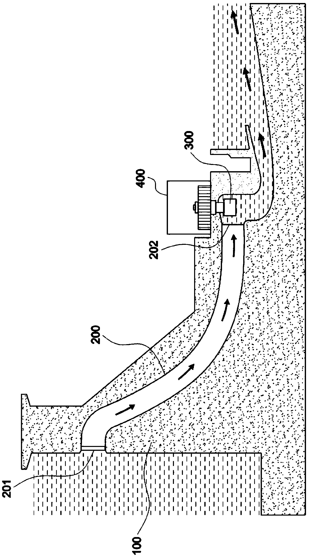
[0060] First, see Figure 3 to Figure 10 As shown, the first feasible embodiment of the present invention includes: a water diversion pipe 20 arranged on the dam 10 of the hydropower station, either inside or above the dam 10 . Its upper end has a water inlet 21, and the bottom end has a water outlet 22; The water outlet 22 utilizes the water diversion pipe 20 to drive the rotating blade 32 ...


PUM


Abstract

The invention discloses a method for improving the power generation efficiency of a water turbine and inhibiting cavitation erosion of spare parts of the water turbine. A gas lead-in device is arranged, high-speed water flow is generated by using the potential energy of a waterhead of a reservoir, the high-speed water flow generates negative pressure at a gas release port of the gas lead-in deviceso that external gas can be sucked in to be mixed with water and pressurization can be implemented at the same time, and water flow with a lot of pressurized bubbles is generated; when the water flowwith a lot of pressurized bubbles is reduced in pressure nearby a water outlet of the water turbine, the pressurized bubbles are depressurized and expand greatly to be larger in size, and the expanded bubbles can assist high-speed water flow in doing work in an impeller to improve the power generation efficiency of the water turbine; and high-speed water flow impacts on guide plates of the impeller of the water turbine to generate a high-pressure area and a low-pressure area. In the high-pressure area, the potential energy and the kinetic energy of water are converted into electric energy, and in the low-pressure area, when partial pressure is lower than the vapor pressure of water, water gasifies to generate cavitation bubbles which cause erosion to the spare parts of the water turbine,and then the efficiency and the service life of the water turbine are affected. With the method, by utilizing the pressurized bubbles in the water flow to increase the pressure in the low-pressure area, and then the cavitation erosion phenomenon is avoided.

Description

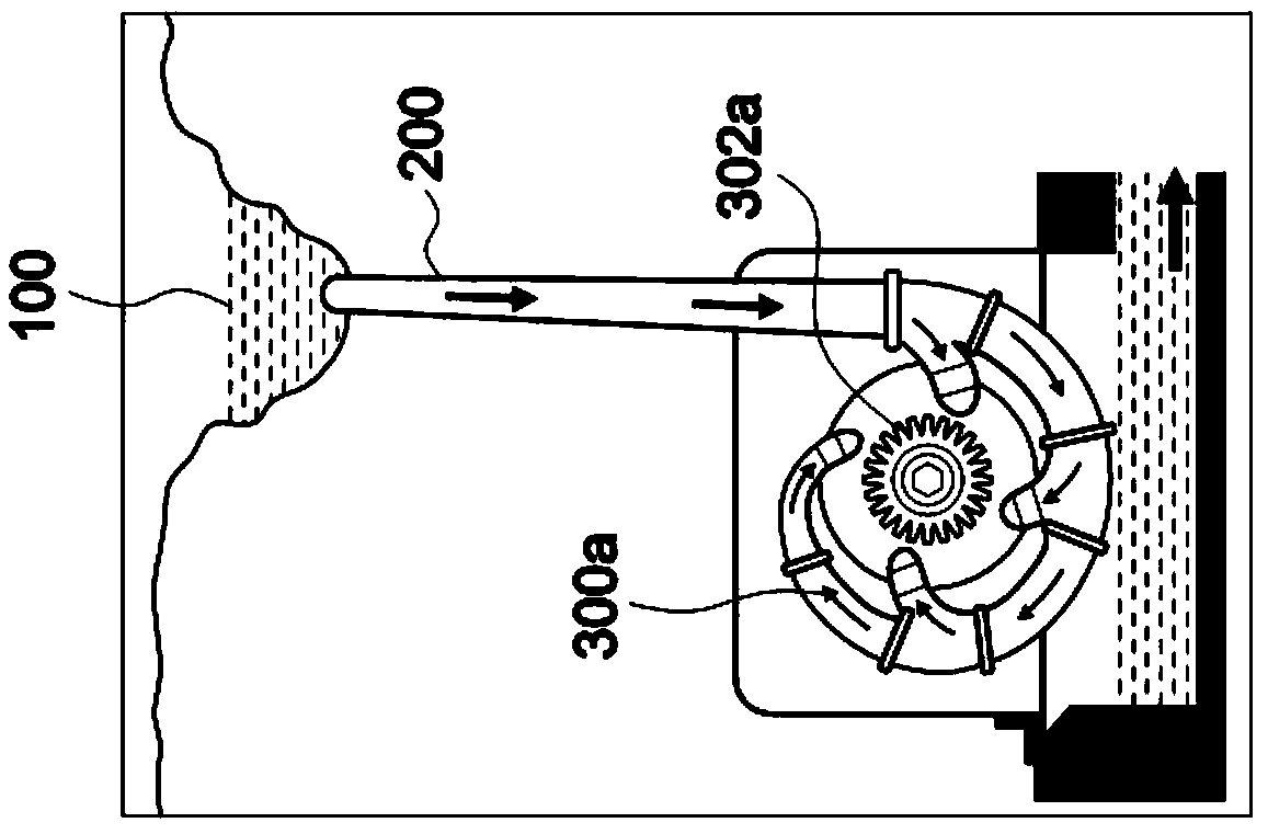
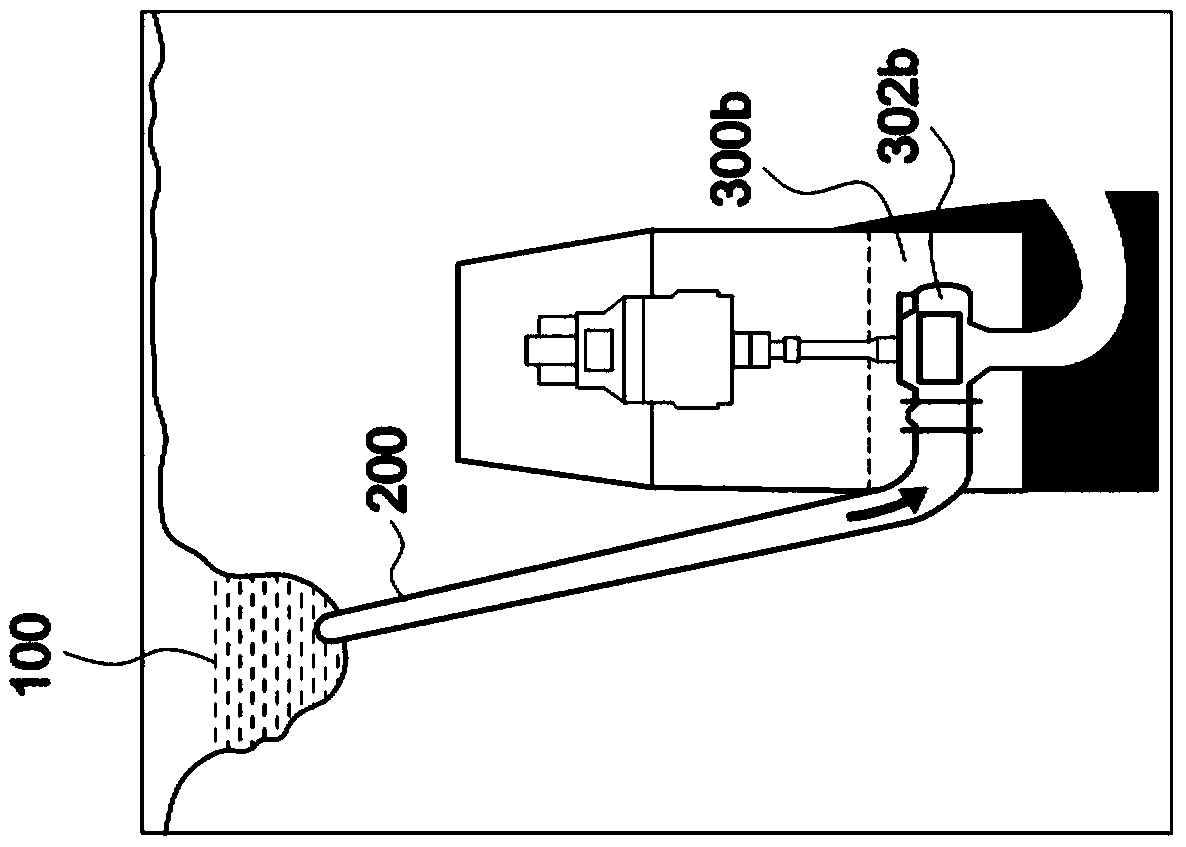
technical field [0001] The invention relates to a method for improving the power generation efficiency of a water turbine and suppressing cavitation erosion of related components such as parts and accessories of the water turbine. Background technique [0002] like figure 1 As shown, the water turbine (Turbine) 300 is through the dam 100 of the hydroelectric power station, the water flow is concentrated, the water is allowed to pass through the water inlet 201 of the water diversion pipe 200, and from top to bottom from the water outlet 202 to the water turbine 300, the impact water turbine 300 rotates, and The generator 400 connected to it is driven by the water turbine 300 to generate electric energy. [0003] Secondly, water turbines can be roughly divided into "impact" turbines and "reverse impact" turbines according to their working principles. Among them, the "impact" water turbine uses high-speed water to impact the rotating blade or water bucket 302a to do work, an...

Claims


Application Information

Patent Timeline
IPC IPC(8): F03B13/08F03B11/04F03B11/00
CPCF03B11/002F03B11/004F03B11/04F03B13/08Y02E10/20
Inventor 林瑞麟
Owner 林瑞麟
Learn More