Mechanical sealing device for rotor pump

A mechanical seal device, rotor pump technology, applied in mechanical equipment, rotary piston type/swing piston type pump components, pump components, etc. Increases service life, improves swing performance, and avoids corrosion effects

Pending Publication Date: 2020-04-17
NINGBO VULCAN TECH CO LTD
View PDF0 Cites 1 Cited by
  • Summary
  • Abstract
  • Description
  • Claims
  • Application Information

AI Technical Summary

Problems solved by technology

The sealing dynamic ring in the above structure rotates with the rotation of the pump shaft, and the sealing static ring and the sealing dynamic ring form a sealing grinding surface to realize the mechanical seal between the inside and the outside of the pump, but the mechanical seal of the above structure has the following disadvantages: compensation structure The springs are all built-in. In this installation method, the springs directly contact the medium, which will cause different degrees of corrosion, and are easy to block and affect the elasticity of the springs, thereby affecting the sealing performance of the entire sealing device; on the other hand, in the size of the mechanical seal In the case of a small size, the size of the spring is limited, and it is easy to fail, so that the spring cannot effectively compensate the static ring, thereby affecting the sealing performance of the mechanical seal device

Method used


Image

  • Mechanical sealing device for rotor pump
  • Mechanical sealing device for rotor pump
  • Mechanical sealing device for rotor pump

Examples


Embodiment Construction

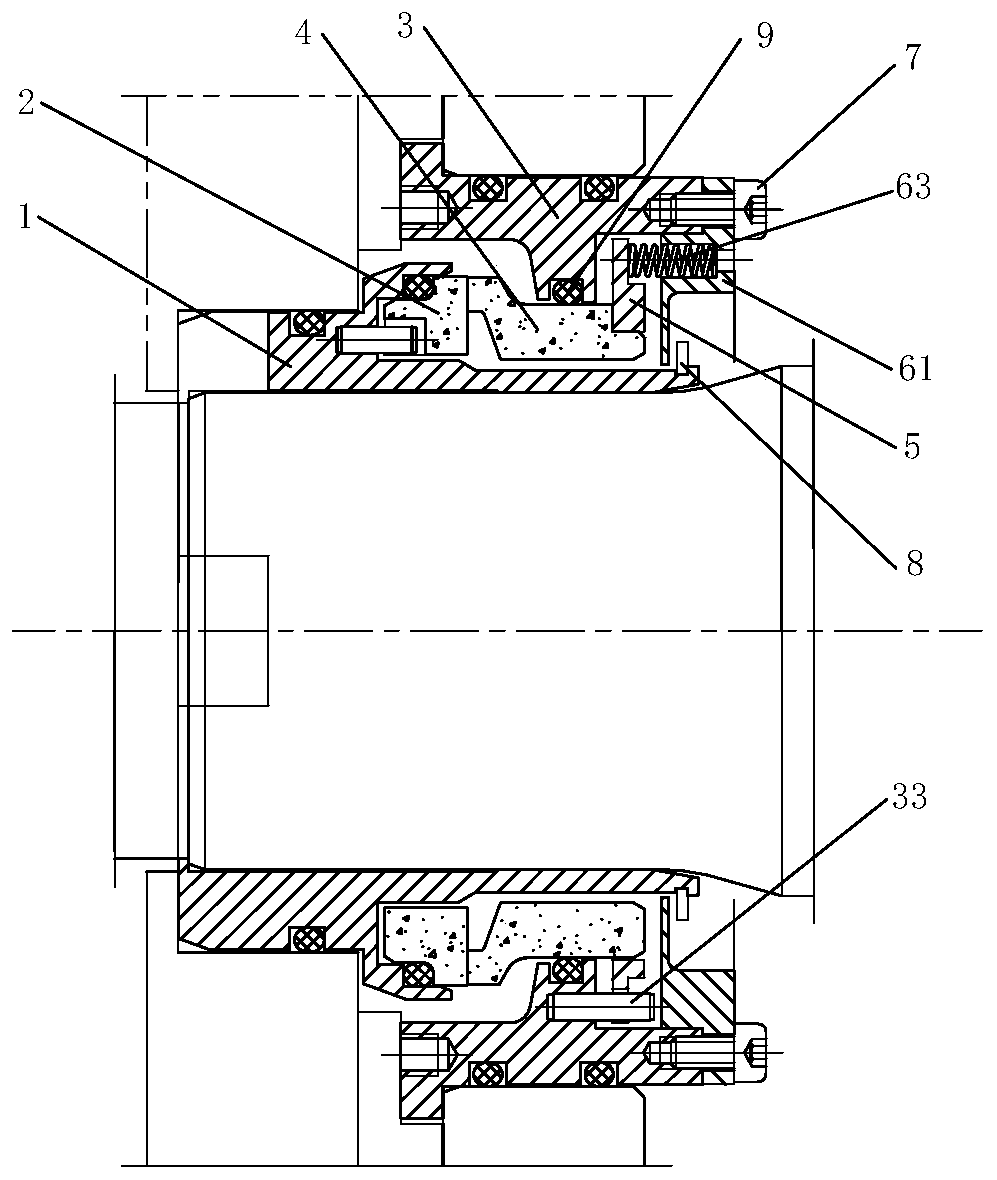
[0035] The present invention is described in further detail below through specific examples, but the present invention is not limited only to the following examples. The inner end referred to in this embodiment refers to the inside of the pump chamber facing the inner side of the gland 3 , and the outer end refers to the outer side of the gland 3 .

[0036] Such as Figure 1-7 As shown, a mechanical seal device for a rotor pump of the present invention includes a shaft sleeve 1, a gland 3, a sealing dynamic ring 2 limited in the circumferential direction on the shaft sleeve, and a sealing static ring 4 sealingly matched with the gland 3. The gasket 5 for circumferential and axial limitation of the static seal ring 4 has a gap between the gland 3 and the gasket 5, and the gasket 5 is radially away from the edge of the static seal ring 4 and the gap between the gland 3 There are at least two compensation components for axially limiting the gaskets connected between them.

[00...


PUM


Abstract

The invention discloses a mechanical sealing device for a rotor pump. The invention aims to provide the mechanical sealing device for a centrifugal pump, and the mechanical sealing device is characterized in that an elastic piece which is not in contact with a medium, and the mechanical sealing device is resistant to corrosion and long in service life. The mechanical sealing device comprises a shaft sleeve, a gland, a sealing moving ring, a sealing static ring, a gasket and at least two compensation assemblies, wherein the sealing moving ring is limited on the shaft sleeve in the circumferential direction; the sealing static ring is in sealing fit with the gland; the gasket is used for carrying out circumferential limiting and axial limiting on the sealing static ring; a gap is formed between the gland and the gasket; the at least two compensation assemblies for axially limiting the gasket are connected between the edge, away from the sealing static ring in the radial direction, of thegasket and the gland; the compensation assemblies are arranged on the edge of the gasket; and the edge of the gasket protrudes outwards, therefore the compensation assemblies do not make contact withthe medium and is prevented from being corroded.

Description

Technical field: [0001] The invention relates to the technical field of mechanical seals, in particular to a mechanical seal device for a rotor pump. Background technique: [0002] Common mechanical seal devices in the industry, including shaft sleeves, glands, sealing dynamic rings, sealing static rings limited in the gland in the circumferential direction, springs for compressing the static rings and providing axial direction compensation, and sealing dynamic rings The circumferential limit is on the shaft sleeve, the sealing dynamic ring is sealed with the shaft sleeve, the sealing static ring is sealed with the gland, the sealing grinding surface is formed between the sealing dynamic ring and the sealing static ring, and the gland is equipped with a compensation spring and a spring set screw. The sealing dynamic ring in the above structure rotates with the rotation of the pump shaft, and the sealing static ring and the sealing dynamic ring form a sealing grinding surfac...

Claims


Application Information

Patent Timeline
Patent Type & Authority Applications(China)
IPC IPC(8): F04C15/00
CPCF04C15/0003
Inventor 邬国平颜碧能谢方民沈赟吴家辉
Owner NINGBO VULCAN TECH CO LTD
Why Eureka
Try Eureka