Material drying device and material drying equipment

A technology of drying device and drying equipment, which is applied in the direction of dryers, dryers, and dryers for static materials, and can solve the problems of high energy consumption, long drying time, and low drying efficiency.

Pending Publication Date: 2020-04-17
王峰云
View PDF0 Cites 0 Cited by
  • Summary
  • Abstract
  • Description
  • Claims
  • Application Information

AI Technical Summary

Problems solved by technology

[0004] The object of the present invention is to provide a material drying device and material drying equipment, which solves the problems of long drying t

Method used


Image

  • Material drying device and material drying equipment
  • Material drying device and material drying equipment
  • Material drying device and material drying equipment

Examples


Embodiment 1

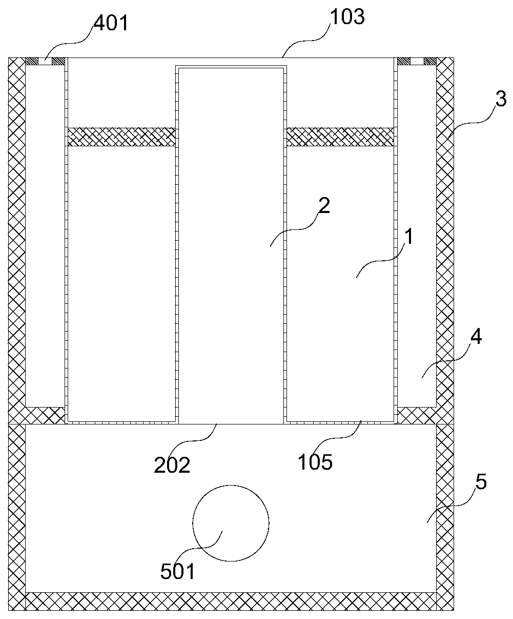
[0040] Please refer to figure 1 This embodiment provides a material drying device, which includes a container 1 for containing particulate matter, and a core body 2 with a hollow structure is arranged in the container 1 . The core 2 is provided with a first air inlet 202 for passing hot air into the core 2, although the first air inlet 202 is as figure 1 As shown, it is installed at the lower part of the core body 2, however, it may be installed at any position of the core body 2. The core body 2 is provided with several first air holes 201, although in this solution the first air holes 201 are all arranged on the side wall of the core body 2, but the first air holes 201 can also be arranged on the side wall of the core body 2 top. A moisture outlet 103 is provided at the top end of the container 1 . By injecting hot air into the first air inlet 202 provided on the core body 2, the hot air will enter the container 1 outside the core body 2 from the first vent hole 201 on th...

Embodiment 2

[0048] The main difference between this embodiment and the above-mentioned embodiment 1 is that the bottom end of the container 1 is not provided with several second air holes 104 , and the opening structure only communicates with the first air inlet 202 of the core body 2 . After the bellows 5 is filled with hot air, the hot air will heat the bottom of the container 1, and the heat at the bottom will still rise to heat the bottom material 7.

Embodiment 3

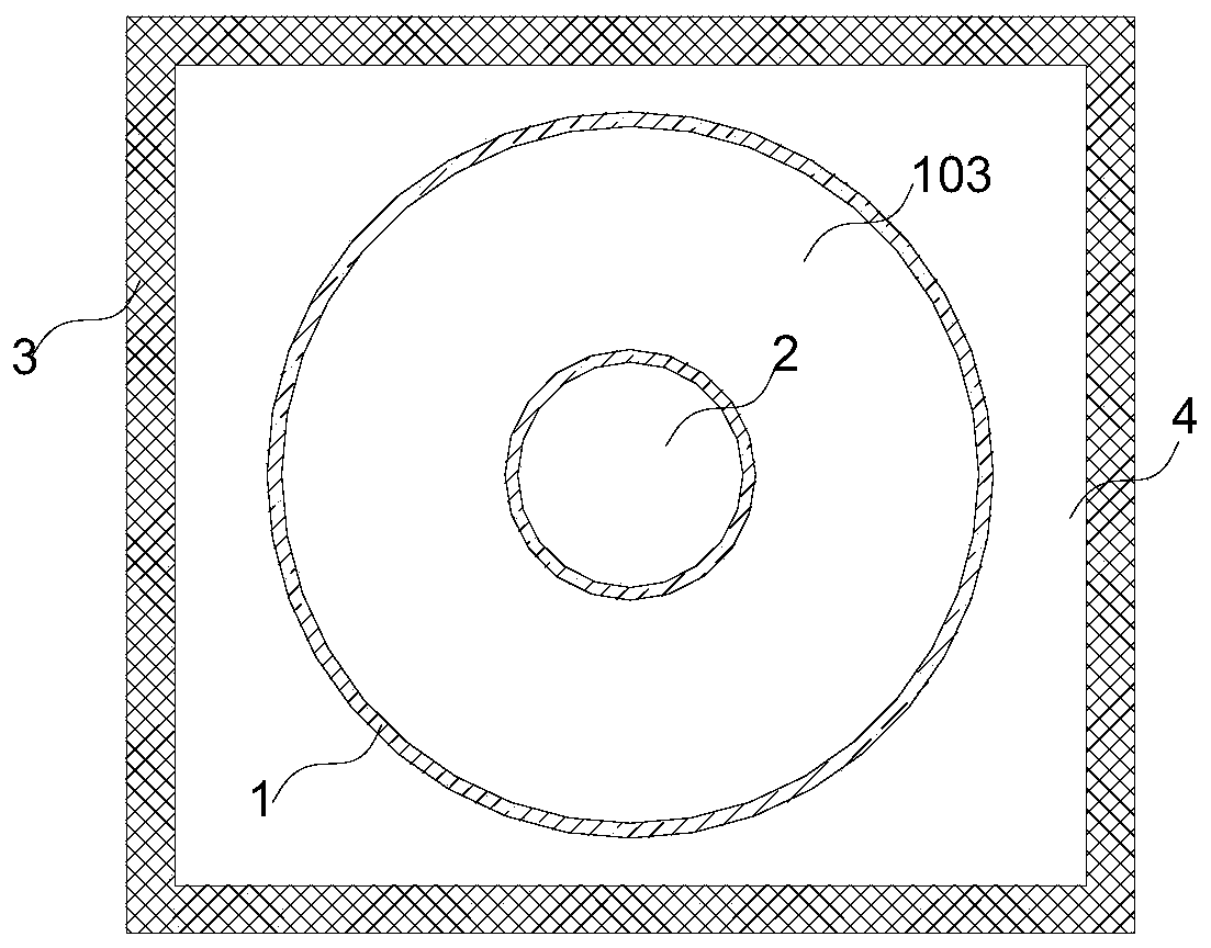
[0050] see Figure 2-7 , The main difference between this embodiment and the above-mentioned Embodiment 1 is that no bellows is provided in this solution. In this solution, the container 1 is sequentially divided into a carrying part 101 and a feeding part 102 from top to bottom, and the bottom of the feeding part 102 is provided with a discharge port. The material 7 after drying in the container 1 is conveniently unloaded through the discharge port. At the same time, the projected area of ​​the blanking part 102 on the bottom surface of the container 1 is smaller than the projected area of ​​the carrying part 101 on the bottom surface of the container 1 . The core 2 corresponds to the carrying part 101 and the blanking part 102 in the container 1 and is divided into an upper part and a lower part from top to bottom, because the projected area of ​​the blanking part 102 on the bottom surface of the container 1 is smaller than that of the carrying part 101 on the bottom surfac...


PUM


Abstract

The invention relates to the technical field of material drying, and discloses a material drying device. The material drying device comprises a container used for containing materials, wherein a corebody of a hollow structure is arranged in the container, the core body is provided with a first air inlet used for introducing hot air into the core body, a plurality of first vent holes are formed inthe core body, and a moisture discharging opening is formed in the top end of the container. According to the material drying device, the moisture discharging opening is formed in the top end of thecontainer, hot air drives a large amount of moisture to be exhausted from the top part, the moisture cannot be accumulated at the top part, and repeated evaporation required by water vapor condensation is avoided.

Description

technical field [0001] The invention relates to the technical field of material drying, in particular to a material drying device and material drying equipment. Background technique [0002] At present, most of the drying methods for materials are drying in a long-distance closed space with hot air, such as tunnel dryers and long-distance drying equipment similar to tunnel dryers. Place the materials to be dried on the shelf, and then place them in the drying equipment. The hot air enters from one end of the drying equipment and the other end of the air. The hot air passes along the length of the drying equipment, and the materials are dried in turn. . [0003] However, for the drying equipment with a length of tens of meters, after the hot air enters from one end, it continuously dries the materials, and the moisture generated during the drying of the materials in the first half of the drying equipment also enters the hot air. In the second half of the drying equipment, b...

Claims


Application Information

Patent Timeline
IPC IPC(8): F26B9/06F26B21/00F26B25/00
CPCF26B9/06F26B21/001F26B25/00
Inventor 王峰云王正宇代素芳
Owner 王峰云
Why Eureka
Try Eureka