Laser range finder

A laser range finder and laser transmitter technology, applied in the field of laser range finder, can solve the problems of complex structure and complicated process of the laser range finder, and achieve the effect of reducing size and cost

Pending Publication Date: 2020-04-17
CHENGDU PULSE OPTICAL
View PDF0 Cites 0 Cited by
  • Summary
  • Abstract
  • Description
  • Claims
  • Application Information

AI Technical Summary

Problems solved by technology

[0003] However, the structure of the existing laser range finder is complicated, and the signal waveform needs to be reshaped and enlarged into a square wave, and then analyzed and processed. The process is complicated. Therefore, how to solve the above problems has become the focus of research in this field

Method used


Image

  • Laser range finder
  • Laser range finder

Examples


Embodiment Construction

[0020] In order to make the purpose, technical solutions and advantages of the embodiments of the present invention clearer, the technical solutions in the embodiments of the present invention will be clearly and completely described below in conjunction with the drawings in the embodiments of the present invention. Obviously, the described embodiments It is a part of embodiments of the present invention, but not all embodiments. The components of the embodiments of the invention generally described and illustrated in the figures herein may be arranged and designed in a variety of different configurations.

[0021] Accordingly, the following detailed description of the embodiments of the invention provided in the accompanying drawings is not intended to limit the scope of the claimed invention, but merely represents selected embodiments of the invention. Based on the embodiments of the present invention, all other embodiments obtained by persons of ordinary skill in the art wi...


PUM

PropertyMeasurementUnit
thicknessaaaaaaaaaa
thicknessaaaaaaaaaa

Abstract

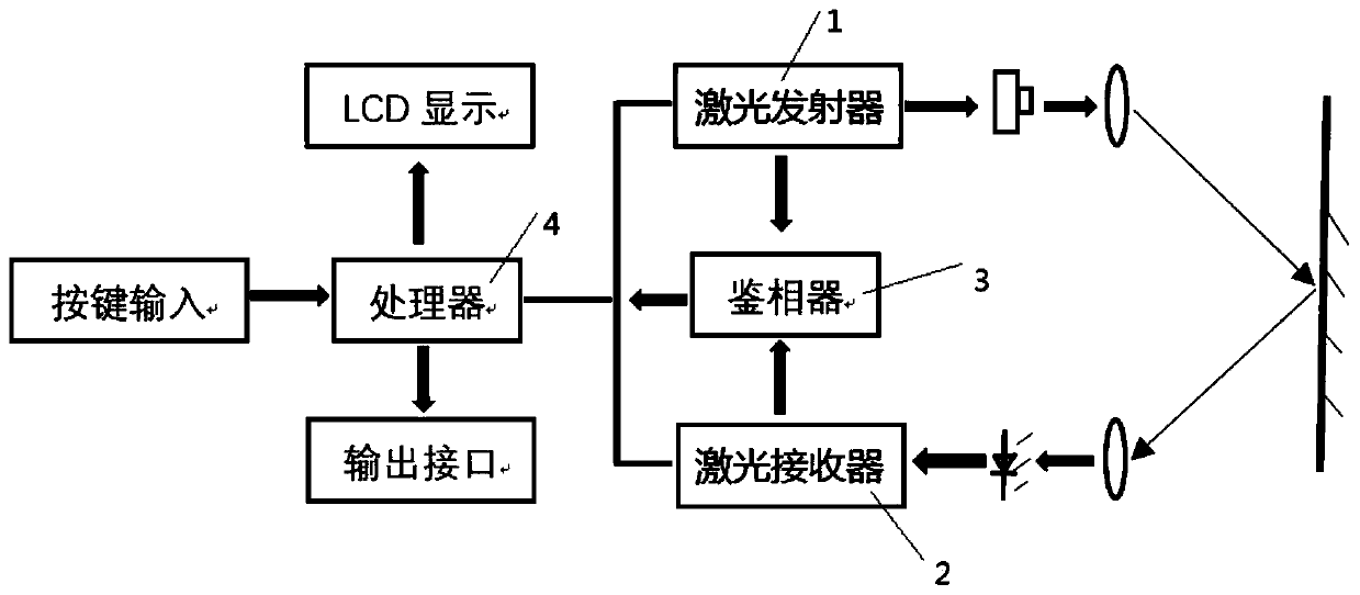
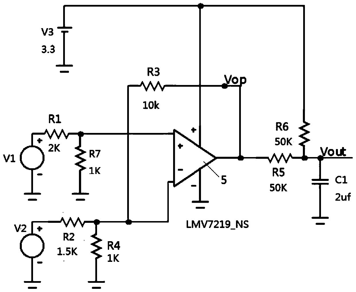
The invention relates to the technical field of laser instruments. The invention discloses a laser range finder. The laser range finder comprises a phase discriminator, and the phase discriminator compares a laser signal emitted by a laser emitter and a laser signal received by a laser receiver through a modulation and demodulation circuit to obtain a phase difference. The modulation and demodulation circuit comprises a comparator, a resistor R1, a resistor R2, a resistor R3 and a resistor R5. The positive electrode signal input end of the comparator is connected with the laser emitter, and the resistor R1 is connected between the positive electrode input end of the comparator and the laser emitter. The negative electrode signal input end of the comparator is connected with the laser receiver, and the resistor R2 is connected between the negative electrode input end of the comparator and the laser receiver. The resistor R5 is connected to the signal output end of the comparator. The resistor R3 is connected between the negative electrode of the resistor R2 and the positive electrode of the resistor R5. According to the invention, the phase information of the signal can be rapidly and accurately extracted through the phase discriminator, so that accurate distance information is obtained.

Description

technical field [0001] The invention belongs to the technical field of laser instruments, in particular to a laser range finder. Background technique [0002] The laser rangefinder uses a laser light-emitting diode to emit a ray of light to the target at a distance, and uses a photoelectric tube to receive the light signal diffusely reflected back from the target. Through signal processing, the time from the emission to the reception of the light is calculated, and the path traveled by the laser is calculated. distance. [0003] However, the structure of the existing laser range finder is complicated, and the signal waveform needs to be reshaped and enlarged into a square wave, and then analyzed and processed. The process is complicated. Therefore, how to solve the above problems has become the focus of research in this field. Contents of the invention [0004] The first object of the present invention is to provide a laser range finder, which solves the shortcomings of t...

Claims


Application Information

Patent Timeline
Patent Type & Authority Applications(China)
IPC IPC(8): G01S17/08G01S7/48G01S7/481
CPCG01S7/48G01S7/4813G01S17/08
Inventor 吴文川李宗毅许方华
Owner CHENGDU PULSE OPTICAL
Why Eureka
Try Eureka