
A mode multiplexing and demultiplexing device, mode demultiplexing method and mode multiplexing method

A technology of mode demultiplexing and mode multiplexing, which is applied in instruments, optical waveguides, optics, etc., and can solve the problems of small process tolerance, high cost, and large size.

Active Publication Date: 2021-05-14
WUHAN POST & TELECOMM RES INST CO LTD +1
View PDF4 Cites 0 Cited by
  • Summary
  • Abstract
  • Description
  • Claims
  • Application Information

AI Technical Summary

Problems solved by technology

The second structure is a directional coupler with a trapezoidal waveguide structure. Although this structure does not require high process precision, it needs to be very long and relatively large in order to obtain better performance.
[0004] For the asymmetric Y branch, it also uses the coupled mode theory. Although this kind of device can be made very small, there are small slits in the Y branch, which have a great impact on the performance of the device, so it is necessary to obtain a good The performance of the device must be made with very high-precision equipment, and the cost is very high
[0005] The existing mode multiplexer / demultiplexer has the problems of small process tolerance, large size, high processing precision and high processing cost

Method used


Image

  • A mode multiplexing and demultiplexing device, mode demultiplexing method and mode multiplexing method
  • A mode multiplexing and demultiplexing device, mode demultiplexing method and mode multiplexing method
  • A mode multiplexing and demultiplexing device, mode demultiplexing method and mode multiplexing method

Examples


Embodiment Construction

[0033] It should be noted that, in the case of no conflict, the following technical solutions and technical features can be combined with each other.

[0034] The specific embodiment of the present invention will be further described below in conjunction with accompanying drawing:

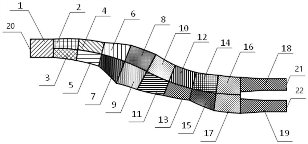
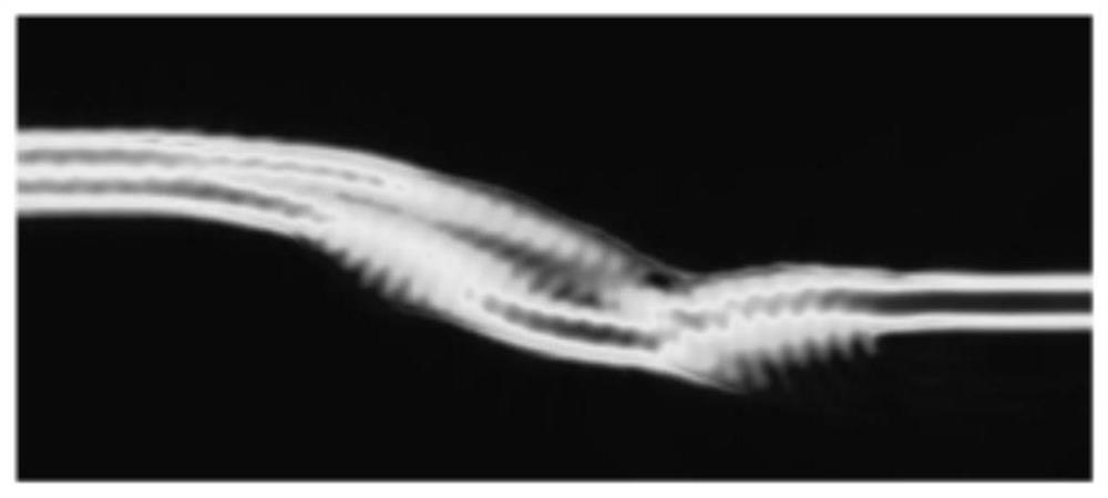
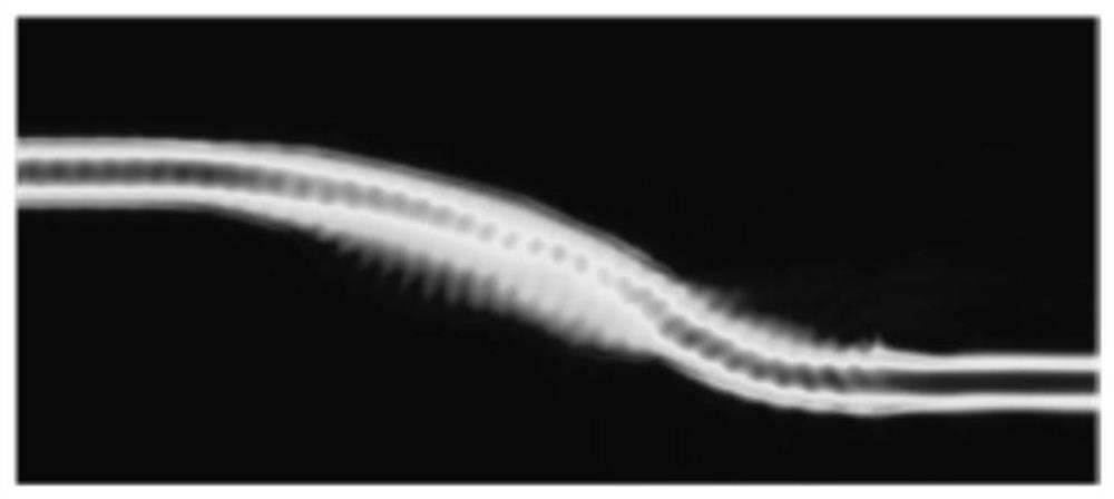
[0035] Such as Figure 1-2 As shown, a mode multiplexing demultiplexer includes: an asymmetric multimode interference waveguide with variable width, a multimode waveguide 1 connected to the left side of the multimode interference waveguide and a multimode interference waveguide connected to the right side of the multimode interference waveguide Two transmission waveguides, the left end of the multimode waveguide 1 forms a first port 20, the right end of each transmission waveguide is a single-mode waveguide, and the single-mode waveguide of each transmission waveguide forms a second port. The two transmission waveguides include a first branch transmission waveguide 18 and a second branch transmiss...


PUM


Abstract

A mode multiplexing demultiplexer, a mode demultiplexing method and a mode multiplexing method, relating to the technical field of optical communication devices, comprising: an asymmetrical multimode interference waveguide with variable width, connected to the multimode interference waveguide The multimode waveguide on the left side of the waveguide and the two transmission waveguides connected to the right side of the multimode interference waveguide, the left end of the multimode waveguide forms the first port, and the single mode waveguide at the right end of each transmission waveguide respectively Form the second port. Beneficial effects of the present invention: by adjusting the shape of the multi-mode interference waveguide, the internal interference point can be adjusted to realize mode multiplexing and demultiplexing. The structure and process tolerance is large, the size is small, there is no fine waveguide structure, and the processing accuracy is not high. , low production cost.

Description

technical field [0001] The invention relates to the technical field of optical communication devices, in particular to a mode multiplexing and demultiplexing device, a mode demultiplexing method and a mode multiplexing method. Background technique [0002] Mode multiplexing / demultiplexing is an important device in applications such as optical communication and optical signal processing. Its function is mainly mode multiplexing or demultiplexing, and can be used in mode multiplexing or polarization multiplexing. There are two main types of mode multiplexers / demultiplexers currently in use: directional couplers or asymmetrical Y-branches. [0003] For the directional coupler, there are two device structures, one is the ordinary straight waveguide directional coupler, in this structure the two waveguides of the directional coupler must strictly meet the phase matching conditions, it is very sensitive to the process, and the process tolerance is low. The second structure is a d...

Claims


Application Information

Patent Timeline
Patent Type & Authority Patents(China)
IPC IPC(8): G02B6/12
CPCG02B6/12004G02B2006/1209G02B2006/12164
Inventor 陈代高肖希王磊张宇光胡晓余少华
Owner WUHAN POST & TELECOMM RES INST CO LTD
Learn More