Supercharge Your Innovation With Domain-Expert AI Agents!

An Ultra-Compact Continuous Zoom Mid-Wave Infrared Optical System

An infrared optical system, a compact technology, applied in the field of infrared optical systems, can solve the problems of easy chipping of tools and materials, difficult control of surface finish and surface accuracy, achieve good imaging quality, improve system transmittance, The effect of good application prospects

Active Publication Date: 2021-12-17
HUBEI JIUZHIYANG INFRARED SYST CO LTD
View PDF6 Cites 0 Cited by
  • Summary
  • Abstract
  • Description
  • Claims
  • Application Information

AI Technical Summary

Problems solved by technology

[0004] With the development and demand of handheld and pod photoelectric equipment, as well as the continuous progress of optical cold processing, precision machining, and coating technology, infrared zoom lenses continue to develop towards small and compact sizes. The absolute length of the zoom optical system puts forward higher requirements. Since the Abbe number of silicon is larger than that of germanium, processing the diffractive surface on the silicon lens can better correct the chromatic aberration. During the process, the vibration between the tool and the material is often prone to problems such as chipping, and the surface finish and surface accuracy are also difficult to control. Often, diffractive surfaces are made on soft materials such as germanium and zinc selenide.

Method used


Image

  • An Ultra-Compact Continuous Zoom Mid-Wave Infrared Optical System
  • An Ultra-Compact Continuous Zoom Mid-Wave Infrared Optical System
  • An Ultra-Compact Continuous Zoom Mid-Wave Infrared Optical System

Examples


Embodiment Construction

[0032] In order to make the objectives, technical solutions and advantages of the present invention clearer, the present invention will be described in further detail below in conjunction with the accompanying drawings and embodiments. It should be understood that the specific embodiments described here are only used to explain the present invention and are not intended to limit the invention.

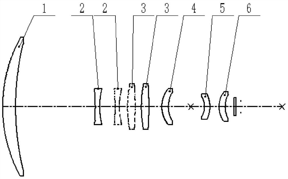
[0033] like figure 1 As shown, the ultra-compact continuous zoom mid-wave infrared optical system of the embodiment of the present invention includes a front group and a rear group, wherein the front group includes a front group lens-1, a zoom mirror 2, a compensation mirror 3, a focus mirror 4, etc. Four lenses, the rear group includes rear group lens 1 5, rear group lens 2 6, a total of two lenses, the imaging beam of the object side passes through the front group lens 1, zoom mirror 2, compensation mirror 3, and focusing mirror 4 in sequence, and then once Imaging, after the rear g...


PUM

PropertyMeasurementUnit
Abbe numberaaaaaaaaaa

Abstract

The invention discloses an ultra-compact continuous zoom mid-wave infrared optical system, which adopts the structural form of secondary imaging, and the secondary imaging component can compress the aperture of the front group lens to meet the efficiency of 100% cold diaphragm, and uses a silicon substrate diffraction element, Greatly simplified structure, the absolute length is only 110mm, which can achieve better imaging quality. The system includes a front group and a rear group. It includes two lenses, and the lens materials are all silicon and germanium, which are commonly used materials in infrared optical systems. During the zooming process, the variable zoom lens and compensation lens are used to move back and forth along the optical axis to achieve the purpose of continuous zooming. The focal length range of the optical lens of the present invention is 70mm ‑240mm, F-number is 4; the lens of the present invention is suitable for high-resolution 640×512 medium-wave cooling detectors, has the characteristics of ultra-compact, small volume, light weight and high resolution, and has good imaging quality at all focal lengths.

Description

technical field [0001] The invention relates to an infrared optical system, in particular to an ultra-compact continuous zoom mid-wave infrared optical system suitable for a high-resolution mid-wave cooling detector. Background technique [0002] Infrared thermal imaging cameras are not affected by adverse weather conditions such as fog and rain, can work around the clock, and adopt a passive working mode with strong anti-interference ability. In recent years, they have developed greatly in military and civilian fields. [0003] The infrared continuous zoom lens can take into account the capture, tracking, monitoring and calibration of the target very well, it can maintain the stability and continuity of the image, the target image will not be lost, and it can remain clear, while taking into account the large field of view search and small field of view Resolution has many applications in various photoelectric loads. [0004] With the development and demand of handheld and ...

Claims


Application Information

Patent Timeline
Patent Type & Authority Patents(China)
IPC IPC(8): G02B15/16G02B15/173
CPCG02B15/16G02B15/173
Inventor 吴耀熊涛柴炎左腾吴学鹏
Owner HUBEI JIUZHIYANG INFRARED SYST CO LTD
Features
  • R&D
  • Intellectual Property
  • Life Sciences
  • Materials
  • Tech Scout
  • Unparalleled Data Quality
  • Higher Quality Content
  • 60% Fewer Hallucinations
Learn More