
Transformer with circulating liquid cooling function

A transformer and circulating fluid technology, applied in the field of transformers, can solve the problems of large power consumption, increased heat dissipation burden, etc., and achieve the effects of improving overload capacity, increasing operating life, and meeting heat dissipation requirements

Inactive Publication Date: 2020-04-17
广州市一变电气设备有限公司
View PDF6 Cites 3 Cited by
  • Summary
  • Abstract
  • Description
  • Claims
  • Application Information

AI Technical Summary

Problems solved by technology

However, the fan is installed outside the transformer, and it is slow to evacuate the heat in the transformer, so it cannot dissipate heat quickly.
In addition, if multiple fans work for a long time, they will consume a large amount of electricity and generate additional heat and noise, which is not conducive to energy saving and environmental protection, but also increases the burden of heat dissipation, and the heat dissipation effect still cannot meet the demand.

Method used


Image

  • Transformer with circulating liquid cooling function
  • Transformer with circulating liquid cooling function
  • Transformer with circulating liquid cooling function

Examples


Embodiment Construction

[0026] Below, the present invention will be further described in conjunction with the accompanying drawings and specific implementation methods. It should be noted that, under the premise of not conflicting, the various embodiments described below or the technical features can be combined arbitrarily to form new embodiments. .

[0027] In describing the present invention, it is to be understood that the terms "upper", "lower", "front", "rear", "left", "right", "horizontal", "vertical", "top", The orientation or positional relationship indicated by "inner", "outer", etc. is based on the orientation or positional relationship shown in the drawings, and is only for the convenience of describing the present invention and simplifying the description, rather than indicating or implying that the referred device or element must have Certain orientations, constructed and operative in certain orientations, therefore are not to be construed as limitations of the invention. In addition, ...


PUM

PropertyMeasurementUnit
thicknessaaaaaaaaaa

Abstract

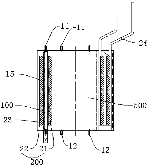
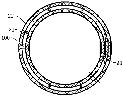
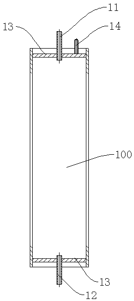
The invention discloses a transformer with circulating liquid cooling function. The transformer comprises a coil and an iron core, wherein the iron core comprises a core column and an iron yoke, the coil is coaxially sleeved on the core column, the core column is fixedly connected with the iron yoke, the coil comprises a high-voltage coil and a low-voltage coil, the low-voltage coil is arranged outside the core column in a sleeving mode, the high-voltage coil is arranged outside the low-voltage coil in a sleeving mode, the transformer further comprises a plurality of cooling pipelines, the cooling pipelines are arranged in the low-voltage coil and the core column respectively, each cooling pipeline is provided with a liquid inlet pipe and a liquid outlet pipe, the liquid inlet pipes are connected with a cooling liquid source, the liquid outlet pipes are connected with a liquid outlet, and cooling water enters the cooling pipelines through the liquid inlet pipes and is discharged through the liquid outlet pipes. According to the transformer, the cooling pipelines are arranged in the low-voltage coil and the core column, so that the low-voltage coil and the core column are filled with the cooling liquid, and the cooling liquid continuously and circularly flows in the cooling pipelines to effectively absorb the heat generated by the transformer in air so as to effectively cool thetransformer.

Description

technical field [0001] The invention relates to the technical field of transformers, in particular to a transformer with a circulating liquid cooling function. Background technique [0002] A transformer is an electrical device that uses the principle of electromagnetic induction to change the AC voltage. Transformers generate a lot of heat during operation. When the transformer is working, more heat is generated, and the temperature of the iron core easily exceeds the specified value of the national standard. When the temperature of the iron core exceeds the specified value of the national standard for a long time, it is easy to cause rapid aging of the insulation layer of the iron core, shorten the life of the iron core, and then affect the normal operation of the transformer. If the heat in the transformer cannot be removed in time, the accumulated heat will easily cause a fire. Therefore, it is very important to cool and dissipate the transformer in time. [0003] Tr...

Claims


Application Information

Patent Timeline
Patent Type & Authority Applications(China)
IPC IPC(8): H01F27/16H01F27/28H01F27/30H01F27/32H01F27/24
CPCH01F27/16H01F27/245H01F27/2876H01F27/306H01F27/324
Inventor 张军海彭景伟郭敬旺莫向松廖冬虹彭志慷彭智绪董记斌孔令斌叶晓锋
Owner 广州市一变电气设备有限公司
Learn More